1. The contacts in the ladder diagram should be drawn on the horizontal line, but not on the vertical branches. As shown in Figure 1(a), since X005 is drawn on the vertical branch, it is difficult to judge the relationship with other contacts. It is difficult to judge the control direction of X005 and output coil Y001, so it should be based on the principle of top-down from left to right. The correct drawing is shown in Figure 1(b)
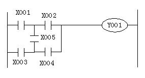
Figure 1 (a)
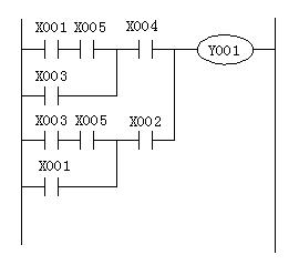
Figure 1 (b)
2. Branches that do not contain contacts should be placed in the vertical direction and should not be placed on the horizontal line. This makes it easy to see the group of contacts and the control route to the output coil to avoid errors during programming. as shown in picture 2.
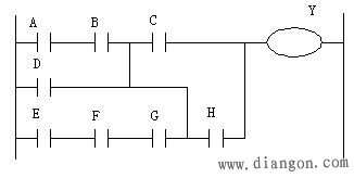
Figure 2 (a) incorrect drawing
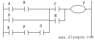
Figure 2 (b) Correct drawing 3. When several series circuits are connected in parallel, the series circuit with the most contacts should be placed at the top of the ladder diagram. When several parallel circuits are connected in series, it should be touched. The one with the most points is placed in parallel to the leftmost side of the ladder diagram, so that the programmed program is clearer and uses fewer instructions, as shown in Figure 3.
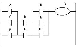
Figure 3 (a) incorrect drawing
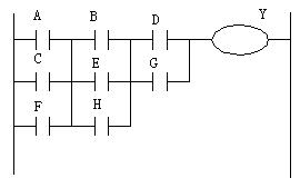
Figure 3 (b) The correct drawing method 4. When programming the ladder diagram, it must be carried out from left to right and from top to bottom.
5. When drawing a ladder diagram, the contact cannot be drawn on the right side of the coil, but only on the left side of the coil, as shown in Figure 4.
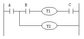
Figure 4 (a) incorrect drawing
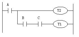
Figure 4 (a) correct drawing six, ladder diagram is reasonable, the use of instructions can be reduced when programming.
Seven, dual output action and its countermeasures
1. Double output operation If the double output (double coil) of the coil is performed in the sequence program, the subsequent operation takes precedence.
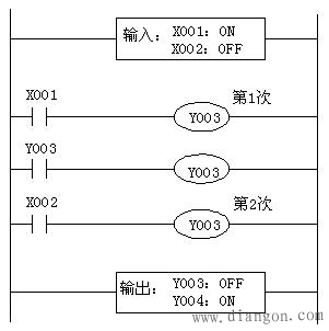
As shown in the figure above: Consider the case where the same coil Y003 is used in multiple places.
For example: X001=ON, X002=OFF
The first Y003, because X001 is turned on, so YOO3 ON. Output Y004 is also ON.
However, the second time Y003, because the input X002 is disconnected, its output is changed to OFF.
Therefore, the actual external output becomes:
Y003=OFF
Y004=ON
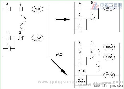
2. Dual Output Countermeasure The dual output (dual coil) does not violate the input in terms of the program, but since the above actions are complicated, the program is changed as shown in the following example.
Patent Vape,E-Cigarette Vape Pens,E-Cigarette Vaporizer Pen,Disposable Vape Puff Bar
Guangzhou Yunge Tianhong Electronic Technology Co., Ltd , https://www.e-cigarettesfactory.com