The basic equipment of a chemical water treatment system of a power plant has good controllability. It is monitored and managed in real time by PLC and industrial control computer. The basic composition of the system is shown in Figure 1.
Three Siemens SIMATIC S5-115U programmable controllers are used to control the primary equipment on site. The program control system is divided into three sets, which are #1 make-up water treatment unit, #2 make-up water treatment unit, and #3 condensate treatment unit. .
The operator station selects two Advantech 586 industrial computers, and the software development platform uses FIX5.5 configuration software from IntelluTIon. FIX5.5 is a complete industrial automation software that can complete data acquisition and control, alarm, graphic data display and other functions. This version runs under WINDOWS or WINDOWSNT environment and adopts graphical user interface. The corresponding internal graphics processing is based on Third generation graphics technology.
The data communication system uses the SINEC L2 network, which connects the SIMATIC series of programmable controllers and industrial computers into a network. SNEC L2 is a token bus network, and the network transmission medium is a twisted pair or optical cable. Each node is connected to the bus network through a bus connector. In this system, data communication is realized between three PLCs and between two industrial computers.
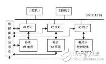
Figure 1 system structure diagram
The configuration of the scheme embodies the advantages of the distributed control system, that is, the control functions are dispersed and the operation management is centralized. The decentralized control function means that the system has fast response in real time and the system is dangerously dispersed, and the operation management is centralized to facilitate centralized management, and the scheme configuration also has redundancy characteristics.
2 PLC and its programming
2.1 SIMATIC S5-115U hardware components and programming summary
The programmable controller SIMATIC S5-115U adopts a standard modular structure. The power supply, CPU, and various I/O modules are all plugged into one motherboard, and the expansion motherboard can be added according to different I/O points. The fine grading of the output module and the memory makes the device have a strong configuration adaptability; the communication between the PLC and the computer can be conveniently realized through the communication processor and the local network.
The programming language of SIMATIC S5-115U is STEP5. There are three expression methods, namely control system flow chart CSF, ladder diagram LAD and statement table STL. The statement table STL is closest to the internal control program of the machine, and the functions are also better than the first two. The method is much richer, so the statement table STL is used in the actual programming application of the system.
The biggest feature of STEP5 is the use of structured programming methods, and provides a large number of standard function blocks such as multiplication function block FB242, communication function block FB244, etc., which greatly simplifies the programming work, and the program is clear and easy to read, modify and test. This advantage is especially evident when programming large and complex programs.
To complete complex tasks, the entire program can be divided into separate blocks. STEP5 has five block types, namely organization block (OB), program block (PB), sequence block (SB), function block (FB) and data. A block (DB), in which an organization block (OB) is used to manage the user program, forms an interface between the operating system and the control program, and all other types of blocks are called for execution here. Function blocks (FBs) are used to implement repeated calls or particularly complex program functions. These function blocks can be provided in the form of standard function blocks or by the user. For example, the standard function block FB242 can realize the 16-bit binary multiplication function, and the FB244 can realize the data transfer between the CPU and the communication processor. When these functions are used, these function blocks can be directly called.
2.2 Design of large-scale SIMATIC S5-115U program
Taking the control program of the system #1 make-up water treatment unit as an example, there are mainly the following statements in the organization block OB1 to complete the unconditional invocation of each function block.
JU FB1 (Defines the data that PLC1 transmits to two industrial PCs)
JU FB2 (Define the data transmitted by two industrial PCs to PLC1)
JU FB231 (Basic setting for communication between PLC1 and two industrial PCs)
JU FB232 (Basic setting for communication between PLC1 and PLC2, PLC3)
JU FB4 (automatic control and bumpless switching)
JU FB3 (pneumatic door and electric door control)
JU FB10 (implementing analog processing function)
JU FB11 (alarm processing)
In FB1 and FB2, the data that needs to be communicated is mainly written into the corresponding bit of a data block such as DB10, so that it can be consistent with the variables in the communication processor. In the FB231, two standard function blocks FB244 (send data) and FB245 (receive data) provided by STEP5 are called, and then the necessary parameters such as interface and job number are filled in according to the communication processor to realize the data communication function. The data to be transmitted between the three PLCs is defined in FB232 according to the data bits allocated by the communication processor. In FB4, according to the production process flow requirements and operating specifications, make full use of the data transmitted by other function blocks and I/O modules to realize the automatic control and non-disturbing switching function of the system; for the similar characteristics of multiple controlled objects, respectively Several representative function blocks FB20, FB30, FB40, for example, call FB20 multiple times in FB4 to solve the problem that a certain step time in the PLC and the display time of the industrial computer screen are consistent, and the multiplication function is called in FB20. Block FB244.FB3 controls the field devices such as pneumatic doors, electric gates and pumps according to the automatic step instructions issued by FB4. FB10 is responsible for the processing of all analog quantities. Here, the FB5.FB11 of the square function block is called to perform alarm processing on the analog quantity according to the data converted by FB10. Here, we must pay attention to the correspondence between the analog quantity and the internal digital quantity of the PLC. Guarantee the accuracy of analog display and alarm.
Distinguish filters according to their spectral characteristics:
Bandpass filter
Shortwave pass (low pass) filter
Long wave pass (high pass) filter
Band-pass filter: select the light of a specific waveband to pass through, and cut off the light outside the passband. The optical indicators are mainly center wavelength (CWL), half bandwidth (FWHM), center wavelength transmittance (Tp), cut-off degree and cut-off range. Divided into narrowband and broadband according to the bandwidth, usually according to the value of the bandwidth than the center wavelength, less than 2% is defined as narrowband, and more than 2% is defined as broadband.
Short-wave pass (also called low pass): Light shorter than the selected wavelength passes through, and light longer than the wavelength is cut off.
Long pass type (also called high pass): Light longer than the selected wavelength passes through, and light shorter than that wavelength is cut off.
Shortpass Filters,Optical Short Pass Filter,Short Pass Filter,Infrared Cut off Filter,Uv Shortpass Filter
Zoolied Inc. , https://www.zoolied.com