Engineers will consider a question: how much data can be transmitted on the channel, or what is the ultimate transmission rate on the specified channel. This is the problem of channel capacity. For example, in an xDSL system, the transmission medium we use is a phone line with only a few megabytes of bandwidth, and the data is transmitted over several megabytes, ten megabits, or even tens of megabits of bandwidth. This high rate guarantees a few megabits of bandwidth. Is the reliable transmission on the twisted pair? Or, from another perspective, how high a data rate (b/S) can be used to reliably transmit information on a physical channel with a given passband bandwidth (Hz)?
As early as 1924, AT&T engineer Henry Nyquist realized that in any channel, the rate of symbol transmission was limited, and derived a calculation formula to estimate noise-free and limited. The maximum data transmission rate of the bandwidth channel, which is today's Nyquist theorem. Since this theorem is limited to calculating the maximum data transmission rate of a channel in a noise-free environment, and still cannot effectively calculate the maximum data transmission rate of a channel in a noisy environment, in 1948, Claude Shannon put Nyquist The special work is further extended to the case where the channel is interfered by random noise, that is, the maximum data transmission rate of the channel is calculated in the case of random noise interference, which is the Shannon theorem today. The two theorems are introduced separately below.
1 Nyquist theorem
Nyquist proved that for an ideal channel with a bandwidth of W hertz, the maximum symbol (signal) rate is 2W baud. This limitation is due to the presence of intersymbol interference. If the transmitted signal contains M status values ​​(the number of states of the signal is M), then the maximum data transmission rate (channel capacity) that the W hertz channel can carry is:
C = 2 & TImes; W & TImes; log2M (bps)
Assuming that the bandwidth transmitted in the W Hertz channel is a binary signal (ie, there are only two physical signals in the channel), the maximum data transmission rate that the signal can carry is 2 Wbps. For example, a voice channel with a bandwidth of 3 kHz is used to transmit digital data through a modem. According to the Nyquist theorem, the sender can only transmit up to 2 & TImes; 3000 symbols per second. If the number of states of the signal is 2, each signal can carry 1 bit of information, then the maximum data transmission rate of the voice channel is 6 Kbps; if the number of states of the signal is 4, each signal can carry 2 bits of information, then The maximum data transmission rate of the voice channel is 12 Kbps.
Therefore, for a given channel bandwidth, the data transmission rate can be increased by increasing the number of different signal units. However, this increases the burden on the receiving end because, each time the receiving end receives a symbol, it no longer distinguishes only one of the two possible signal values, but must distinguish one of the M possible signals. The noise on the transmission medium will limit the actual value of M.
2 Shannon's theorem
Nyquist considers the ideal channel without noise, and Nyquist's theorem states that when all other conditions are the same, the channel bandwidth is doubled and the data transmission rate is doubled. But for noisy channels, the situation will quickly deteriorate. Let us now consider the relationship between data transmission rate, noise and bit error rate. The presence of noise can destroy one or more bits of data. If the data transmission rate is increased, the time taken per bit will be shorter, and therefore the noise will affect more bits, and the bit error rate will be larger.
For noisy channels, we hope to improve the signal strength to improve the receiver's ability to receive data correctly. The parameter to measure the quality of the channel is Signal-to-Noise RaTIo (S/N). The signal-to-noise ratio is the ratio of the signal power to the noise power presented at a particular point on the channel. Usually the signal-to-noise ratio is measured at the receiving end because we are processing the signal at the receiving end and trying to eliminate the noise. If S is used to indicate signal power and N is used to represent noise power, the signal-to-noise ratio is expressed as S/N. For convenience, people typically use 10log10 (S/N) to represent the signal-to-noise ratio in decibels (dB). The higher the value of S/N, the better the quality of the channel. For example, S/N is 1000, its signal-to-noise ratio is 30 dB, S/N is 100, its signal-to-noise ratio is 20 dB, S/N is 10, and its signal-to-noise ratio is 10 dB.
For the transmission of digital data over noisy channels, the signal-to-noise ratio is very important because it sets a reachable data transmission rate upper limit for noisy channels, ie for channels with a bandwidth of W hertz and a signal-to-noise ratio of S/N. , its maximum data transmission rate (channel capacity) is:
C = W × log 2 (1 + S / N) (bps)
For example, for a voice channel with a bandwidth of 3 kHz and a signal-to-noise ratio of 30 dB (S/N is 1000), no matter how many level signals are used to transmit binary data, the data transmission rate cannot exceed 30 Kbps. It is worth noting that Shannon's theorem only gives a theoretical limit, and the rate that can be achieved in practical applications is much lower. One of the reasons is that Shannon's theorem only considers thermal noise (white noise) without considering factors such as impulse noise.
Shannon's theorem gives the error-free data transmission rate. Shannon also proved that, assuming that the actual data transmission rate of the channel is lower than the error-free data transmission rate, it is theoretically possible to use an appropriate signal coding to achieve a error-free data transmission rate. Unfortunately, Shannon did not give a way to find this code. It is undeniable that Shannon's theorem does provide a standard for measuring the performance of actual communication systems.
After speaking the two theorems, the explanation of coding and modulation is attached.
Source and sink
Sources and sinks are two professional terms in the network. In fact, sources and sinks can be simply understood as senders of information and recipients of information. The process of information dissemination can generally be described as: source → channel → sink. In the traditional information dissemination process, there are strict restrictions on the qualification of the source, usually refers to the radio station, television station and other institutions, using a central structure. In a computer network, there is no special restriction on the qualification of the source. Any computer in the network can be a source. Of course, any computer in the network can also become a sink.
Coding and modulation
Due to the limitation of the transmission medium and its format, the signals of the two communicating parties cannot be directly transmitted, and must be processed in a certain manner so that it can be adapted to the characteristics of the transmission medium, so that it can be correctly transmitted to the destination.
Modulation refers to the use of analog signals to carry digital or analog data; and coding refers to the use of digital signals to carry digital or analog data.
The existing transmission channels mainly include analog channels and digital channels. The analog channels are generally only used to transmit analog signals, while the digital channels are generally only used to transmit digital signals. Sometimes, if necessary, it may be necessary to transmit analog signals by digital channels or digital signals by analog channels. In this case, we need to convert the transmitted data to the type of data that the channel can transmit, that is, analog signals and numbers. Signal conversion, which is the main content of coding and modulation. Of course, the problem of how analog data and digital data are transmitted through the channel is also an important part of coding and modulation. In the following, we introduce the modulation and coding of data from analog signals using analog channels, analog signals using digital channels, digital signals using analog channels, and digital signals using digital channels.
1. Analog signals are transmitted using analog channels
Sometimes analog data can be transmitted directly on the analog channel, but this is not commonly used in network data transmission. People still modulate the analog data and then send it over the analog channel. The purpose of modulation is to modulate the analog signal onto a high frequency carrier signal for long distance transmission. At present, the existing modulation methods mainly include Amplitude Modulation (AM), Frequency Modulation (FM), and Phase Modulation (PM).
2. Analog signals are transmitted using digital channels
To transmit an analog signal on a digital channel, the analog signal is first converted into a digital signal. The process of this conversion is a digital process. The digitization process mainly involves two steps of adoption and quantization. Common methods for encoding analog signals into digital channel transmission are: Pulse Amplitude Modulation (PAM), Pulse Code Modulation (PCM), Differential Pulse Code Modulation (DPCM), and Increment. Pulse Modulation (DM).
3. Digital signals are transmitted using analog channels
The process of transmitting a digital signal using an analog channel is a process of modulation, which is a process of changing the characteristics of an analog signal by digital data represented by a digital signal (binary 0 or 1), that is, a process of modulating binary data onto an analog signal.
A sine wave can be defined by three characteristics: amplitude, frequency and phase. When we change any of these features, there is another form of wave. If the original wave is used to represent binary 1, then the deformation of the wave can represent binary 0; vice versa. Any of the three characteristics of the wave can be changed in this way, so that we have at least three mechanisms for modulating digital data into analog signals: Amplitude-Shift Keying (ASK), frequency shifting Frequency-Shift Keying (FSK) and Phase-Shift Keying (PSK). In addition, there is a mechanism that combines amplitude and phase changes called Quadrature Amplitude Modulation (QAM). Among them, quadrature amplitude modulation is the most efficient, and it is also the technology often used in all modems.
4. Digital signals are transmitted using digital channels
If the digital signal is transmitted on a digital channel, the digital signal needs to be encoded first. For example, this is generally the case when data is transferred from a computer to a printer. In this manner, the digital signal must first be encoded, i.e., the binary 0 and 1 digital signals produced by the computer are converted into a series of voltage pulses that can be transmitted over the conductor. Encoding the source can reduce the data rate and improve the information efficiency. Encoding the channel can improve the anti-interference ability of the system.
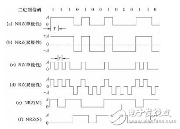
At present, common data coding methods mainly include non-return to zero code, Manchester coding and differential Manchester coding.
(1) Non-Return to Zero (NRZ, Non-Return to Zero): The binary digits 0 and 1 are respectively represented by two levels, commonly -5V for 1, and +5V for 0. The disadvantage is that there is a DC component, the transformer cannot be used in transmission; there is no self-synchronization mechanism, and external synchronization must be used for transmission.
(2) Manchester Code: 0 and 1 are represented by changes in voltage, and hopping occurs in the middle of each symbol. High to low transitions represent 0, and low to high transitions represent 1 (note: some tutorials have opposite descriptions of this section and are correct). A jump occurs in the middle of each symbol, and the receiver can extract this change as a synchronization signal. This type of encoding is also known as the Self-Synchronizing Code. The disadvantage is that double the transmission bandwidth is required (ie the signal rate is twice the data rate).
(3) Differential Manchester coding: hopping still occurs in the middle of each symbol, with or without hopping at the beginning of the symbol to indicate 0 and 1. There are jumps that represent 0 and no jumps that represent 1 (note: some tutorials have opposite descriptions about this part and are correct).
For most wooden speakers, the material used is MDF medium density fiberboard, which is made of wood fiber or other plant fibers after crushing, fiber separation, drying, and then applying adhesive, and then hot pressing. An artificial board. The density is uniform, the surface is smooth, and the thickness is 5-30 mm. This type of sheet has excellent physical properties, is easy to decorate and process, so it is widely used in the manufacture and production of speakers. Some cabinets use multi-layer boards. Compared with MDF, multi-layer boards are lighter in weight and have better firmness. The sound effect of the speakers is also better, but the price is relatively expensive. They are mainly used in some professional stage speakers.The wooden speakers are also very beautiful in appearance and design, and they will give people an elegant feeling when used.Our company's wooden speaker products not only have high quality and competitive prices, is a Chinese supplier trusted by buyers all over the world market, choose us and you have chosen a bright and brilliant future
Wooden Speaker,Wooden Bluetooth Speaker,Wooden Soundbar,Wooden Phone Speaker
NINGBO LOUD&CLEAR ELECTRONICS CO.,LIMITED , https://www.loudclearaudio.com