Currently, medical appliance OEMs are developing more specialized personal care devices for the treatment and monitoring of common diseases. These products are reasonably priced and greatly improve the quality of health care. MCUs play an important role in portable medical devices such as home sphygmomanometers, spirometers, pulse oximeters, and heart rate monitors. The actual physiological signal in most of these products is an analog signal that needs to be amplified, filtered, etc. before being measured, monitored or displayed.
Embedding high-performance analog peripherals into ultra-low-power MCUs not only enables on-chip systemization of portable medical electronics, but also extends battery life. This article describes various ways to simplify the analog front-end design of portable battery-powered medical devices, such as combining high-performance peripherals such as op amps, ADCs, and DACs with low-power MCUs. The MCU has digital filtering and processing functions, and can also display physiological data such as blood pressure, vital capacity, heart rate and blood oxygen content. Combining these peripherals with the MCU not only performs all of the above functions, but also meets power requirements by turning off the peripherals into standby mode (current consumption is only a few mA).
A good example is that its 16-bit RISC CPU not only provides the required signal processing power, but also has an ultra-low operating current that allows the battery to last for years in such applications. The MCU integrates peripherals such as op amps, 12-bit multi-channel ADCs, and dual 12-bit DACs as part of the analog signal processing circuitry. In addition to embedding high-performance analog peripherals, the device features 120KB of on-chip flash and Universal Serial Communication Interface (USCI). The following is a detailed introduction to a single-chip solution for medical products with integrated analog peripherals.
sphygmomanometerFigure 1 is a functional block diagram of a sphygmomanometer. This application typically uses a bridge pressure transmitter as a sensor and is connected to an inflatable cuff. The transmitter can be activated via a port pin and can save significant power since it is only activated during pressure measurement. The mV output of the sensor is proportional to the pressure. This signal needs to be amplified before digitization and then measured by the ADC. The amplified signal detects the Korotkoff tone and determines the systolic and diastolic pressure readings. The three op amps in the MCU do the job well. A high gain differential amplifier block of several amplifiers eliminates common mode noise in the application. The differential amplifier function block using 3 amplifiers is shown in Figure 2. The amplified signal is input internally to the 12-bit ADC. The DMA peripherals in the device enable efficient data processing, enable fast execution of Korotkoff tone detection algorithms, and filter out noise that affects measurement results. The 16-bit CPU handles the above algorithm with lower MIPS processing power. The device also integrates a 160-segment LCD driver with a regulated charge pump to provide stable contrast, further complementing this single-chip solution. The 120KB low-power flash memory in the MCU can be upgraded in the field, and since the flash has in-system programmability, it can be used as a data logger. The USCI serial port in the device can communicate with a PC or PDA to download recorded data. Due to the ultra-low power architecture of the MCU, the solution operates at less than 3mA in blood pressure measurement mode. In Idle mode, the device is operating normally and shows that the real-time clock consumes less than 3mA.
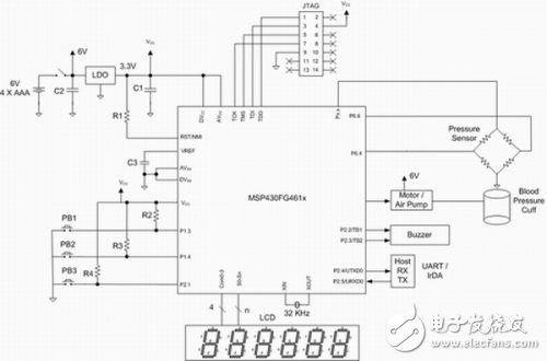
The DC motor controlled by the PWM output charges the deflated bag. This is the only place where the sphygmomanometer uses a 6V power drive motor. If the power requirements are not met, the entire sphygmomanometer can be powered by a 3V lithium-ion button battery. However, only a few motors are currently powered by this high-impedance button battery, so this example can provide 3.3V power to the MCU using four common low-cost AAA alkaline batteries and a low-dropout regulator (LDO). Assuming two measurements of blood pressure per day, these batteries can be used for two years. The MCU can work in the active display timing mode for a long time because the current consumption of this mode is very small. In addition, the user does not increase the current consumption when viewing the stored blood pressure readings. In addition, the integrated dual-channel DAC is capable of producing a sine wave with a phase shift of 180°, which improves transmitter performance.
SpirometerThe spirometer, also known as the Pulmonary Function Test (PFT) device, is used to test lung capacity in medical diagnostics. In this application, the measured parameter is the amount of air flow over a certain expiratory time in liters per minute. The sensor used is a pneumatic transmitter, which is actually a differential pressure transmitter. The spirometer is similar to the sphygmomanometer design except that no inflation motor is required. Three MCU op amps are used as sensor amplifiers for measuring airflow. The rest of the spirometer is designed to be simple. The role of the 12-bit ADC is to measure the airflow and compare it to the stored normalized values. Flash memory helps store a variety of standardized values, making the design suitable for a variety of situations. Figure 1 can be used as a reference design for the spirometer (the transmitters used in the system are similar). Please note that the spirometer does not require motor control. In addition, the MCU's low power consumption extends battery life, and its high integration reduces cost and increases system reliability.
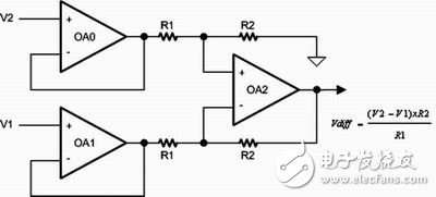
Figure 2 Differential Amplifier
Pulse oximeter and heart rate monitorHeart rate monitoring and pulse oximetry use more than one technique. This article focuses on non-invasive optical plethysmography. This oximeter uses an external probe with an MCU to display blood oxygen saturation and pulse rate. In this application, the same sensor can be used for both heart rate detection and pulse oximetry. This technique provides a simple and accurate way to estimate arterial oxygen saturation and heart rate. The probe is placed in different parts of the body such as fingertips, earlobes and nose. The probe contains two light-emitting diodes (LEDs), one of which emits visible red light (660 nm) and the other emits infrared light (940 nm) (see Figure 3). The beam passes through the body tissue to the photodetector. When passing through human tissues, hemoglobin in red blood cells absorbs some of the light, and the amount of absorption varies depending on the oxygen saturation. First, by measuring the amount of light absorbed by two wavelengths, the MCU can accurately calculate the proportion of oxidized hemoglobin. Secondly, the light passing through the human tissue contains a pulse component generated by the difference in arterial blood volume caused by the heartbeat.
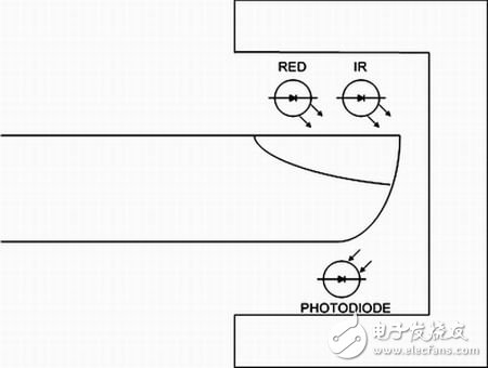
Figure 3 is equipped with two probes
These two LEDs must be driven with a constant current source to ensure a constant brightness during the measurement. A constant current source with automatic gain control (AGC) feedback can be obtained by using an internal DAC and a simple MCU algorithm. The MCU is able to select the amount of absorption of the pulsating portion of the blood, and arterial blood, non-pulsating blood or capillary blood, and other human tissue pigments absorb light. The latest measurement technology reduces the effects of interference when measuring oxygen saturation. The two LEDs are periodically turned on, the red LED is turned on, then the infrared LED is turned on, and the last two are turned off, repeating several times per second. This time division multiplexing technique eliminates background noise interference. The phase orthogonal multiplexing technique allows the red and infrared rays to be separated first by phase (rather than time) and then combined. This more advanced technology has the potential to eliminate atmospheric interference from motion or electromagnetic interference because the two LED signals differ in phase when recombined.
The average blood sample saturation can be measured, and the pulse rate can be calculated by the number of LED cycles between consecutive pulsating signals, and the average pulse rate is approximately the same as the time at which the saturation average is obtained, which is related to the specific monitor.
The ratio of the two parameters is calculated from the absorption ratio of the two frequencies of light. A series of experimentally obtained blood oxygen saturation values ​​were stored in the MCU flash memory (the oxygen content of the breathing gas increased gradually during the experiment). The MCU compares the measured ratio of the two wavelengths of light absorption to the stored value and then displays the oxygen saturation as a percentage. Normally, the oxygen saturation value is between 70% and 100%, and the data below 70% is estimated because the data of human blood oxygen content below 70% cannot be obtained.
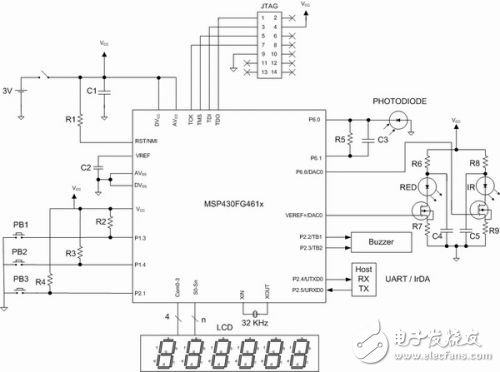
Figure 4 Pulse oximeter based on MSP430FG461x
The structure diagram of the pulse oximeter based on MSP430FG461x is shown in Fig. 4. The application has a complete analog front end solution including integrated op amps, ADCs and DACs. The DAC and the on-chip reference circuit form a constant current source that drives the LEDs. One of the operational amplifiers is used as an I/V converter for the sensor photodiode. Automatic gain control is achieved by adjusting the LED brightness using a DAC output and a software algorithm executed by the MCU. The ADC digitizes the amplified and filtered output signal, and the software in the MCU calculates the average. So far, the red light, infrared light source and the data acquisition and calculation of the ratio of both sides have been completed. This ratio is compared to the stored standard data to obtain an accurate blood oxygen saturation value. The calculated blood oxygen percentage value is displayed on the LCD. The A/D conversion value also contains heart rate information, and the software can calculate the heart rate average in about 5s, which is also displayed on the LCD. In addition, the PWM output of the MCU drives the pressure buzzer, which emits a brief beep every time the heart beats. Through this periodic beep, it can be judged whether the sensor position and signal acquisition are normal.
ConclusionIn the portable medical applications described above, the ultra-low power microcontroller MSP430FG461x has a number of advantages as a single-chip solution. The high precision of the ADC is easy to meet the needs of measurement applications. On-chip op amps and DACs are very helpful for signal conditioning and automatic gain control. After selecting the appropriate MCU for the measurement application, the system designer will proceed with the software development. Because the MCU can provide on-chip emulation, designers can debug in real time through the JTAG port. A variety of compilers and debuggers are available, and the debugger hardware is inexpensive. The debugger hardware requires a simple logic level shifter to connect to the PC parallel port without the need for a traditional ICE interface. Full-featured real-time emulation can set breakpoints on the chip's built-in hardware, enabling full-speed operation while debugging. The device's high level of integration and code development convenience significantly reduce system design costs. The program code in the flash memory can be refreshed at any time during debugging, which greatly shortens the development time. Therefore, selecting the MCU can effectively shorten the time to market. In addition, 120KB of in-system programmable flash memory can be used as a data logger at the same time.
Product Characteristics
1) This Controller is compatible with Wii U console and incompatible with Wii Console .
2) The Controller is connected to the Wii U console via Bluetooth wireless. Within the effective working distance of 8 meters, the signal is stable, no delay and no dropping.
3) No need to install any driver, the handle can be used when it is connected with the Wii U host.
4) This handle supports all functions of the original Wii U Pro handle.
5) Built-in motor to support vibration feedback function.
6) Built-in 400 mAh lithium-ion battery, which can supply power for less than 10 hours after full charge.
7) Built-in four LED channel indicator lights, which can be used to number players in the order of connecting to the computer.
8) Up to four handles can be connected to the host at the same time.
9) Ergonomic design, feel comfortable, even if continue to play games for several hours is not easy to fatigue.
10) Each handle is equipped with a USB charging data line for charging the handle.
11) When the handle is operated without any action, it goes into dormancy for about 5 minutes, and the indicator light of the handle goes out.
Product Use
1) Press the power button of the handle. If the four LED channel lights do not flicker, it means that the handle has no electricity and needs to be charged first.
2) Open the Wii U host and connect the necessary accessories, such as the display.
3) Open the handle: Press the power key of the handle, and the four LED channel lights will flicker quickly.
4) Press SYNC in front of the Wii U host, then SYNC on the back of the handle. An LED lamp on the handle will be long on, indicating that the code is successful and the handle can be used.


Wii U Pro Controller,Wireless Controller,Wii U Pro Wireless Gamepad,Wii U Pro Wireless Controller
Shenzhen GEME electronics Co,.Ltd , https://www.gemesz.com