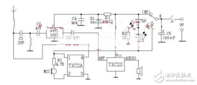
As shown in the figure, the transmitting module adopts TXC2A type, the module has 5MHz frequency adjustment range; the receiving module uses TXC2S type, the nominal sensitivity is 5μV, the receiving frequency and volume can be adjusted, the maximum working voltage is 9V, and it has static Noise function, no noise when standby. In order to further improve the sensitivity and expand the scope of use, the author added a high-level circuit composed of μPC1651 at the antenna end. Since the μPC1651 does not have a large operating current, only a 5V Zener diode is used for power supply. It can also be replaced by 78L05. When installing the μPC1651, it is necessary to comply with the principle of high-frequency circuits, otherwise it is prone to self-excitation.
The circuit is normally turned on, in the standby state, the receiving module and the high-level circuit work, and the light-emitting tube D2 is lit (green). The receiving module has a squelch function, which is quiet and power-saving. When receiving a call and needs to answer, press K, the power is applied to the TXC2A, the LED D3 (red) is lit, and the TXC2A is working while receiving part of the power supply. Disconnected, at this time speaking to the MIC, the whole work process is a simplex intercom.
Although the machine does not use crystal oscillator to stabilize the frequency, its module design is reasonable and the frequency is relatively stable. The power supply can be supplied by the battery 9V or the AC rectified 7809 voltage regulator. Do not touch the antenna when using it. I have been working properly for more than a week. If the running frequency occurs over a long period of time, fine-tune the capacitor on the receiving module. The system can reach a distance of more than 100 meters.
The machine is easy to assemble. When the module is purchased, the manufacturer will give the pin function of the module. The transceiver switch can be self-made, and the finished product can also be used. The antenna uses a 1/4 wavelength rod antenna. After the user connects the picture, the fine-tuning frequency of the two machines can be received by each other. It is better to put the circuit into the metal box, and then lead the volume potentiometer on the receiving module to the metal panel to change the volume at any time!
The following is the circuit diagram of the FM wireless microphone, the circuit is very simple, there is no redundant device. The high-frequency triode V1 and the capacitors C3, C5, and C6 form a three-point capacitor oscillator. For beginners, we do not want to honing the specific working principle of the capacitor three-point type. We only need to know that this circuit structure is a high-frequency oscillator. The load of the collector of the triode C4, L constitutes a resonator, and the resonant frequency is the transmission frequency of the FM microphone. According to the parameters of the components in the figure, the transmission frequency can be between 88 and 108 MHz, which covers the receiving frequency of the FM radio. The value (stretch or compression coil L) can be easily changed to avoid the FM station. The transmitted signal is coupled to the antenna via C4 and transmitted.
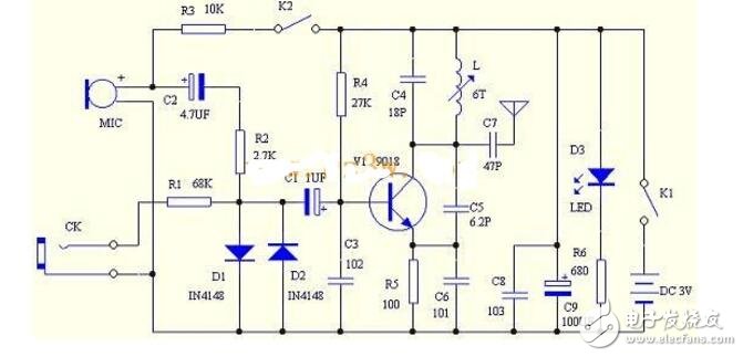
R4 is the base bias resistor of V1, which provides a certain base current to the triode, so that V1 operates in the amplification region, and R5 is a DC feedback resistor, which functions to stabilize the working point of the triode.
The frequency modulation principle of the FM microphone is to achieve frequency modulation by changing the capacitance between the base and the emitter of the triode. When the sound voltage signal is applied to the base of the triode, the capacitance between the base and the emitter of the triode will follow. The size of the sound voltage signal changes synchronously, and at the same time, the transmission frequency of the triode changes, and frequency modulation is realized.
The microphone MIC can collect the external sound signal. Here we use the electret small microphone, which has very high sensitivity and can collect weak sound. At the same time, the microphone must work with DC bias to work. The resistor R3 can provide certain The DC bias voltage, the greater the resistance of R3, the weaker the sensitivity of the microphone to collect sound. The smaller the resistance, the higher the sensitivity of the microphone. The AC sound signal collected by the microphone is sent to the base of the triode through C2 coupling and R2 matching. In the circuit, the two diodes D1 and D2 are connected in anti-parallel, mainly functioning as a bidirectional limiting function. The diode's turn-on voltage is only 0.7V. If the signal voltage exceeds 0.7V, it will be shunted by the diode. This ensures that the amplitude of the sound signal can be limited to plus or minus 0.7V. Excessive sound signals will cause the transistor to pass. Modulation, producing sound distortion and even not working properly.
CK is an external signal output socket, which can be used to introduce an external sound signal source such as a TV headphone jack or a Walkman headphone jack into a frequency-modulated transmitter through a dedicated connection line. The external sound signal is sent to the triode base through R1 attenuation and D1 and D2 limiting. The frequency is modulated by the pole. So this kit can not only be used as a wireless microphone, but also as a TV wireless headset.
The LED D3 in the circuit is used to indicate the working state. When the FM microphone is powered, it will light up. R6 is the current limiting resistor of the LED. C8 and C9 are power supply filter capacitors. Because the large capacitance is generally made by the winding process, the equivalent inductance is relatively large. A small capacitor C8 in parallel can reduce the high frequency internal resistance of the power supply. This circuit is very common.
In the circuit, K1 and K2 are actually a switch. It has three different positions. When the dial is to the left, the power is turned off. On the far right, K1 and K2 are connected to be used as the FM microphone. The middle position is K1 and K2 is disconnected. Do use as a wireless repeater, because the use of a wireless repeater is that the microphone does not work, but the microphone consumes a certain amount of quiescent current, so disconnecting K2 can reduce power consumption and extend battery life.
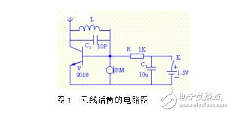
Introduce a simple wireless microphone. Wireless transmission can be performed in the FM broadcast band. This unit can be used for monitoring, signal forwarding and e-learning. Because of its simple structure and easy assembly, it is suitable for beginners.
First, the wireless microphone circuit diagram and working principle
The electret microphone converts the sound into an audio current, which is applied to a high frequency oscillator composed of a transistor V, a coil L and a capacitor C1 to form a frequency modulated signal that is transmitted from the antenna to the space. In the range of 10 meters, it is received by a radio with an FM broadcast band (FM band), and is restored to the original sound through a speaker to realize wireless transmission of sound.
China leading manufacturers and suppliers of DC Support Capacitors,DC Capacitor, and we are specialize in Electrolytic capacitor,High Voltage Capacitor, etc.DCMJ DC Support Capacitors
DCMJ DC Support Capacitors,Capacitors High Voltage,Dc-link Filter Capacitor,Dc Film Capacitors
YANGZHOU POSITIONING TECH CO., LTD , https://www.yzpstcc.com