Just like the plane coordinates of junior high school, it needs to be represented by x and y. When you go to high school or university, you only need to use a "number" v, but this v is a "vector" composed of two numbers of x and y... The modulo and differential modes are the attributes of the "input signal" as a whole, and the differential input can be expressed as
Vi=(vi+, vi-) can also be expressed as vi=(vic, vid)c for common mode and d for differential mode. Both descriptions are completely equivalent. Just change the angle of understanding, just like the coordinate transformation in geometry, the coordinates of the same point in different coordinate systems are different, but always the same point. The common-mode input range of the op amp: the range of common-mode signals allowed by the device (op amp, instrument, etc.) to maintain normal amplification (keeping a certain common-mode rejection ratio CMRR). Obviously, there is no problem with the common mode voltage at "one end". But "one end" also has the same problem of input voltage range. And this range is equal to the common mode input voltage range.
The reason is simple: when the op amp is working normally, the two inputs are virtual and short, and the single-ended input voltage range is almost the same as the common-mode input voltage range.
For other amplifiers, the common-mode input voltage is different from the single-ended input voltage range. For example, for the instrument, the differential input is not 0, and the common mode input voltage range in actual operation is smaller than the single-ended input voltage range.
Can be understood as:
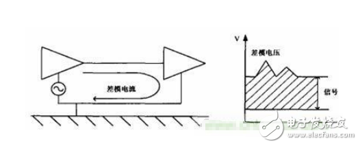
The two boats were still on the water, standing two people, A and B. A and B pull each other. When the ship fluctuates up and down, A can feel the tension of B change. The difference in height between the two ships is the differential mode signal.
When the water level rises or falls, A does not feel the tension. The absolute height of the two boats from the bottom of the water is the common mode signal.
Thus, we say that A and B only respond to the differential mode signal and not to the common mode signal. Of course, there is also a certain common mode range. If it is too low, it will sink to the bottom of the water, so that the ship can no longer fluctuate. Too high will cause the water to overflow and form a water flow that will prevent the ship from staying on the water.
In theory, A and B should only respond to the differential mode.
But in fact, because the ship is bumping up and down, both A and B are dizzy, obviously only the common mode, but it has an illusion: it seems that the other party is moving relative to itself. This shows that the internal forces of A and B are weak, and the common mode rejection ratio is not good. It’s a joke, but it’s roughly what it means.
Of course, the differential mode voltage should not be too large, otherwise it will cause A and B to be pulled apart.
Mainly this sentence "common mode is the arithmetic mean of the two inputs, the differential mode is the direct difference between the non-inverting end and the inverting end".
The common mode voltage should be the common value added to the input of the amplifier circuit when viewed from the source, and the differential mode is the difference applied to the two inputs of the amplifier circuit. The common mode voltage is DC and there is also AC. DC is called DC common mode rejection (ratio), and AC is called AC common mode rejection (ratio), collectively called common mode rejection (ratio). A general amplifier, especially an instrumentation amplifier, has better DC common-mode rejection, but for AC common-mode rejection, the frequency is often too high----a sharp drop, that is, the frequency response is not good. The general signal has a source impedance, which can damage the symmetry of the circuit to varying degrees. Therefore, be careful of the error caused by the differential amplifier. Refer to the relevant data book.
Not just in op amp circuits. As long as it is electrical signal transmission, it can be divided into common mode and differential mode. The common mode is the common mode between the two signal lines. Therefore, as long as there is signal transmission, the common mode interference is accurate. The modulo and the differential mode are superimposed and cannot be distinguished. Only the two-line transmission can distinguish the common mode and the differential mode. The origin of the common mode and the differential mode is the value of this distinction.
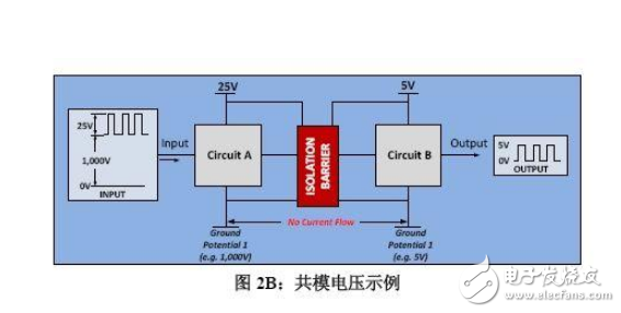
1. Conducted interference: Assuming that the common reference point ("ground") of the system is disturbed, the potential fluctuates. In fact, the concept of potential is strictly speaking only relative meaning. There is no "potential" in an isolated point, so the fluctuation must be relative to another reference point, for example: the earth, or the reference point of the device connected to your board or the whole machine. . At this time, the interference on the two signal lines between the two devices is approximately the same.
2. Under spatial coupling interference: electromagnetic waves have a certain spatial continuity. In a small space, electromagnetic waves can be considered to be uniform. If the two wires are close together, the interference of the two wires is approximately the same. According to the general statement, any signal line is interfered with the ground line, which is common mode interference. However, the distinction between common mode and differential mode is valuable only when transmitting in two lines. Moreover, a line can have "common mode" but no differential mode. Of course, the concept is also artificial. Either by accepted terms (factual standards) or by authority, for example, IEEE standards.
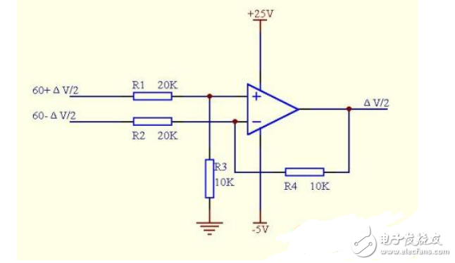
Let's take another example to look at: differential amplifier op amp plus 3v end 2v equivalent to one end plus vd=0.5vc=2.5 end plus: vd=-0.5vc=2.5
Any kind of signal is a combination of common mode and differential mode, but what determines which common mode is the differential mode is the reference signal. It is meaningless to simply talk about a line. The reference ground is actually a signal of 0.
If one end is a VI, then the ground terminal is equivalent to a common mode signal of VI/2, and the differential mode signal is -VI/2. When combined, it is 0. If any reference bit is V2, the common modulus in the VI should be ( V1+V2)/2, the differential modulus is (V1-V2)/2
The other end is equivalent to the common modulus (V1+V2)/2, and the differential modulus is -(V1-V2)/2. It is meaningful to compare the differential mode with the common mode.
Simple understanding: After you have chosen a land, the relative height of the two lines is the differential mode. The average of the absolute heights of the two lines is the common mode. When the distance between the two lines is reduced to 0 and becomes a line, there is only one height, so its absolute value is the common mode.
In addition, there are some definitions in publicly published academic journals, which are understood by various authors for reference:
1. Common mode interference refers to the AC signal that the interference voltage appears at the end (positive or negative) of the meter's input end to the ground. It can be connected to the end of the input end of the meter by the transistor voltmeter (positive or negative). Between the ground and the ground, the general ground disturbance is mostly in the range of several volts to tens of volts.
2. Common mode interference refers to the interference generated by the simultaneous intersection of two measured points in the circuit relative to the ground, and the differential mode jf is the relative change of the potential difference between the two measured points in the circuit. Interference
3. Common mode interference refers to the interference voltage common to the two input terminals of the analog-to-digital converter. It may be DC or AC voltage. The voltage amplitude can be several volts or higher depending on the application environment. Common mode interference is also called Common-mode interference, commonly used common mode rejection ratio (CMRR), indicates the ability of the input circuit to suppress common mode interference.
4. Common mode interference refers to the interference in the loop formed by the phase line and the ground line of the power supply. Differential mode interference refers to the interference in the loop formed by the phase line and the phase line of the power supply. The conducted interference is mainly caused by the high speed in the circuit. High-frequency oscillation caused by the interaction between switching voltage, current and stray parasitic parameters
5. In fact, the conducted interference has the common mode and the differential mode. The so-called common mode interference refers to the ground line and the phase line interference signal. The phase between the lines is the same and the potential is equal, and the differential mode interference is the phase interference signal phase. Poor 180 (equal potential)
6. Common mode interference refers to the interference (potential) formed between a certain point of the protection device and the ground (or casing), as shown by Vt in Figure 1. It is important for the protection device to work abnormally. Reason 7. Common mode interference means that the interference is in the same direction and direction. It exists in any relative ground of the power supply or between the neutral and the earth. Common mode interference is also called longitudinal mode interference, asymmetric interference or grounding interference. It is a carrier fluid and Interference between the earth
Rocker Switches
Rocker Switches is also called a boat switch, an IO switch, and a power switch. The structure of the rocker switch is the same as that of a Toggle Switches and Slide Switches, except that the handle of the rocker is replaced by a ship. This On Off Rocker Switches often used as the power switch of electronic equipment. Its contacts are divided into single-pole single-throw and double-pole double-throw, and some switches also have indicator lights.

It is a household circuit switch hardware product. Custom Rocker Switches are used in drinking fountains, treadmills, computer speakers, car batteries, motorcycles, plasma TVs, coffee pots, plugs, massage machines, etc., involving commonly used household appliances.

It can divided into Momentary Rocker Switch and square Rocker switches with plastic material,second two-foot boat switch, second three-legged boat switch, three-speed three-legged boat switch, three-speed six-legged boat switch, two-speed six-legged boat switch , round boat switch, square boat switch.
Rocker Switches,Round Rocker Switch,Carling Rocker Switch,Kenworth Rocker Switches
YESWITCH ELECTRONICS CO., LTD. , https://www.yeswitches.com