Speaking of headphones, I think a lot of people are running with its excellent sound insulation, sound effects, etc., but traditional wired headphones will always accidentally pull the headphone cord during use, sometimes even directly It’s quite uncomfortable to pull the earphones off your head and smash it to the ground.
After repeatedly making these unpleasant things happen, I finally decided to change my wireless headset! The ambition is on a shopping trip to buy a circle, swept a slap in the balance of the book, and then silently grab the ordinary wired headset to continue to use ... feeding, as a DIYer how can allow this to happen! Can't afford to buy it? Hurry to purchase parts to start!
Materials and tools:
Materials
headphones
One pair of old headphones (for taking audio cables)
Bluetooth audio receiver module
600mAh lithium battery and protection circuit
Lithium battery charging board
3pin pin header and socket
3.5mm headphone holder
Small toggle switch
Several flying lines
Heat shrinkable tube
Oily marker
Insulation Tape
Blue 5mm LED
Production tool
Soldering iron and related consumables
Hot melt glue gun
Electric grinder (with drill)
Sickle
Vernier caliper
Steel ruler
Small Phillips screwdriver
Disassemble the original headphones
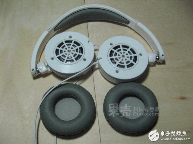
First take the earmuffs down, be careful not to be too violent, moderately strong, don't pull the stitches above...
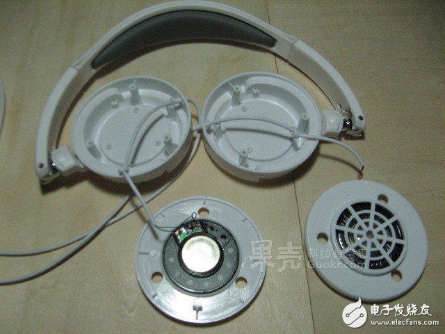
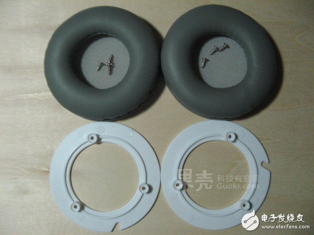
Then remove the three fixing screws and gently and gently remove the speaker unit. The removed screws can be placed inside the earmuffs, which is not so easy to lose. After half an hour, the total assembly will find fewer screws.
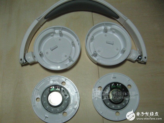
Solder the original audio wire and remove it, leaving the outer casing and speaker section.
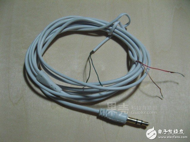
Connect the relatively independent left and right parts with the old headphone cable
Since the left and right sides of the original earphone are relatively independent, there is no wire connection, and the production needs to separate the battery and the bluetooth module on the left and right sides, and the left channel output of the Bluetooth module placed on the right side also needs to be connected by the audio cable. On the left, you need to use an old pair of headphones to remove the audio cable.
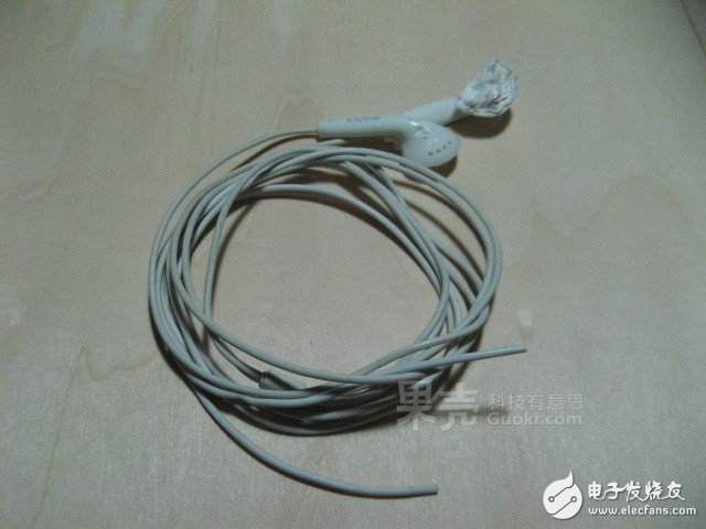
This is a pair of headphones that have been smashed. Fortunately, the cable is not damaged and can be used.
The reason why the headphone cable removed from the pair of headphones is not used here is because the removed line is too thick, and it is not convenient to route, and the line of the ordinary earphone is relatively thin.
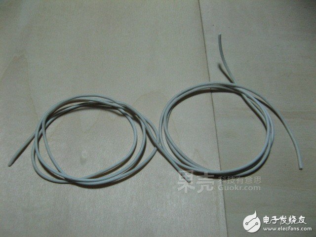
Divide two equal length earphone cords approximately twice the length of the headphone cover.
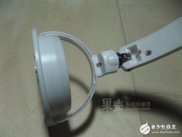
Disassemble the folding shaft and telescopic part of the earphone. Be careful not to use brute force when disassembling. If it is not open, check whether a screw is removed and try several directions and angles. Otherwise, After you slam, you only have to buy a new headset...
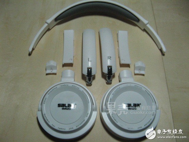
Fully disassembled folding shaft and telescopic section.
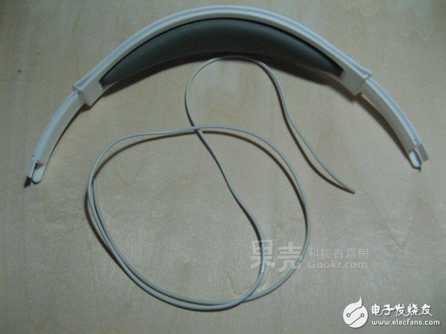
Start with the hood part and prepare the wiring.
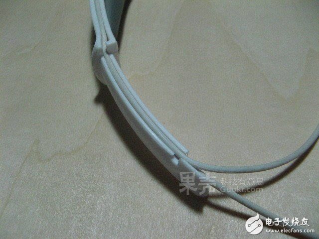
As shown in the figure, when the headphone cable is pressed into the hood, it suddenly appears that the earphone seems to have been designed with a cable trunking. The earphone cable can be easily pressed in, and even the telescopic and folding shafts have a wire slot. Convenient for this production...
Then click on a line, as shown in the figure, one is the power line and the other is the left channel audio line.

The wire is then passed around the latches on the hood to prepare for advancement into the card slot.
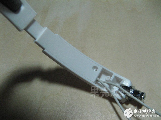
Push the teeth of the hood into the slots of the telescopic section, and then thread the two wires out of the gap at the bottom end of the telescopic section (right side in the figure). Be careful to pull the hood up to the longest to leave a line long enough to prevent the line from being torn off when the earphones are adjusted for tightness.
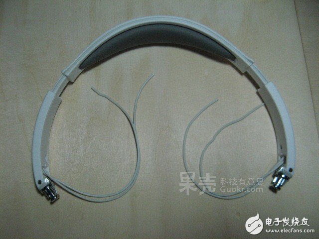
On the other side, follow the same method, pay attention to the length of the lines left at both ends!
The earmuffs were partially mounted, but it was found that the originally designed wire trough of the metal shaft part of the figure can only accommodate one wire and cannot pass through two wires. At this time, only the hole on the outer casing of the earpiece is perforated. ...
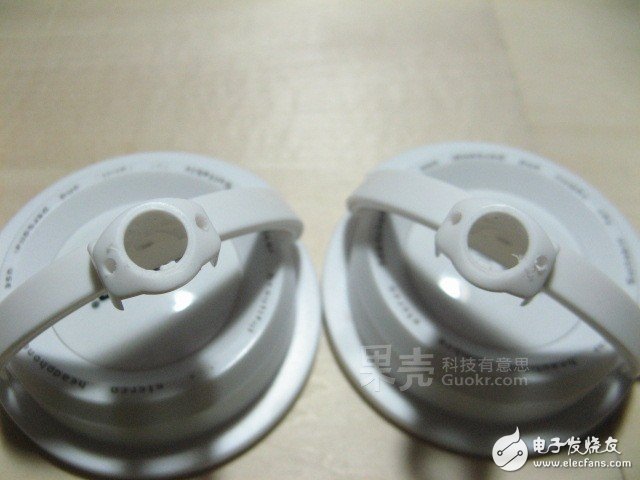
Weigh the diameter of the wire and prepare a bit that is slightly larger than the wire diameter (about 0.1 mm in size) and punched.
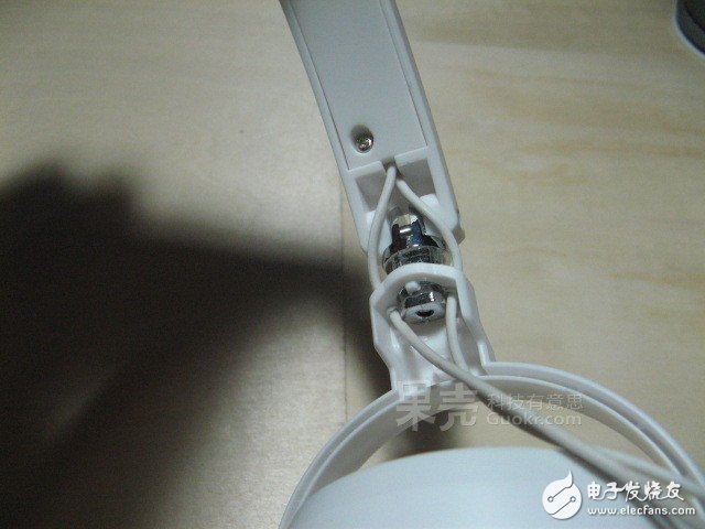
Pass the two earphone cables through the wire hole respectively, and the cable is successful!
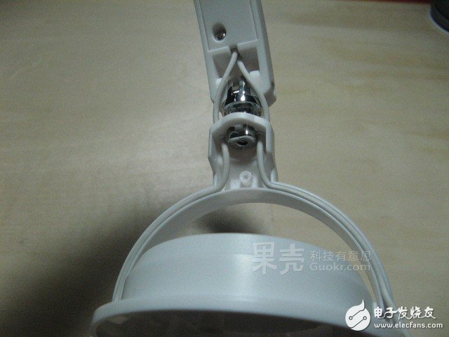
Press the down headphone cord into the gap inside the handset hinge bracket as shown.
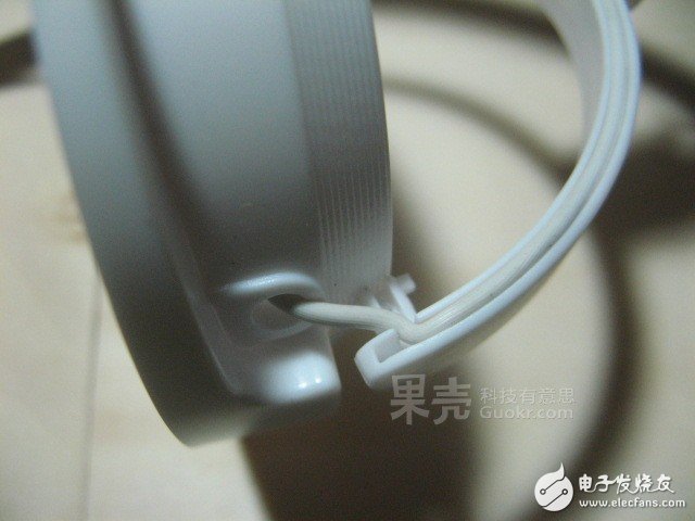
As for the side of the shaft, first remove the shaft, then put the headphone cord in, and then put the shaft back.
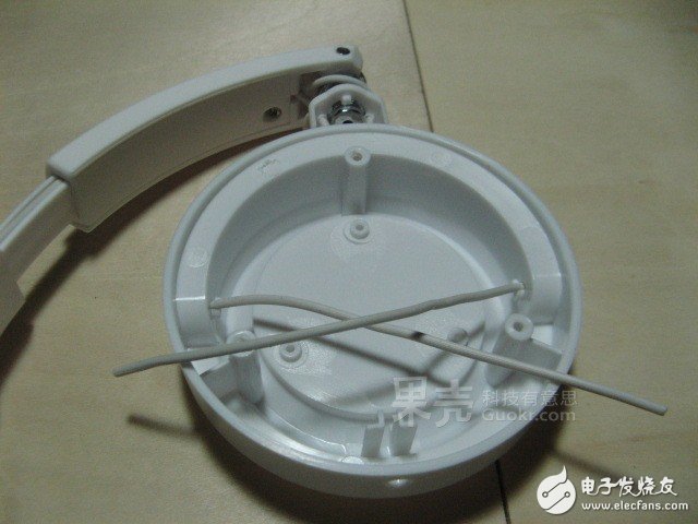
After two thousand hardships, I finally successfully penetrated the two earphone cables inside the earpiece...
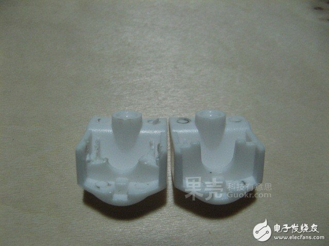
Since the hole is punched through the shaft part, the replaced shaft clamp should be properly trimmed to leave a certain space for the "invasion" incoming earphone cable.
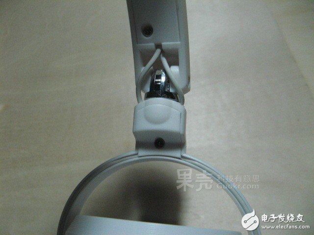
Then put the trimmed clips on, and the wiring of the folding shaft part is over~
The other side is also the same, the basic framework of a headset Bluetooth headset comes out~
Circuit part production
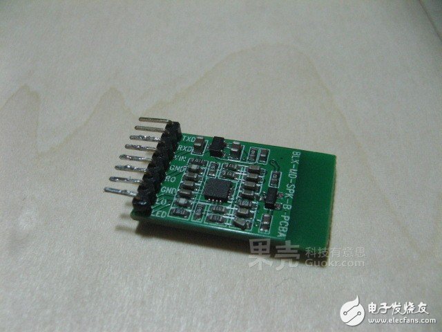
The first to appear is today's protagonist - Bluetooth audio receiver module.
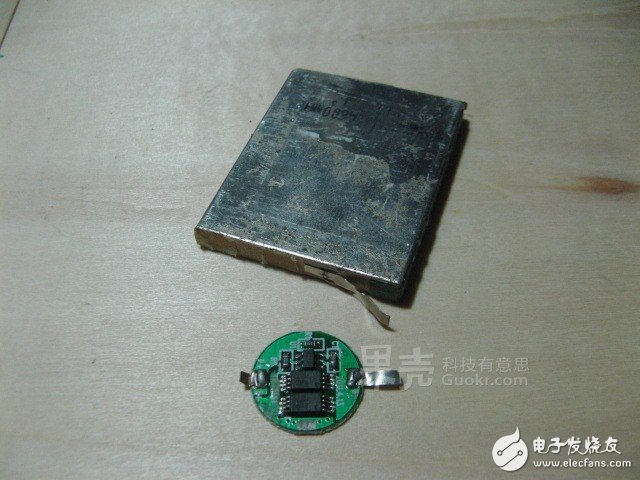
Then there is the power source of the protagonist - the old cell phone battery of 600mAh (say that the cell is more appropriate...) and the lithium battery protection circuit.
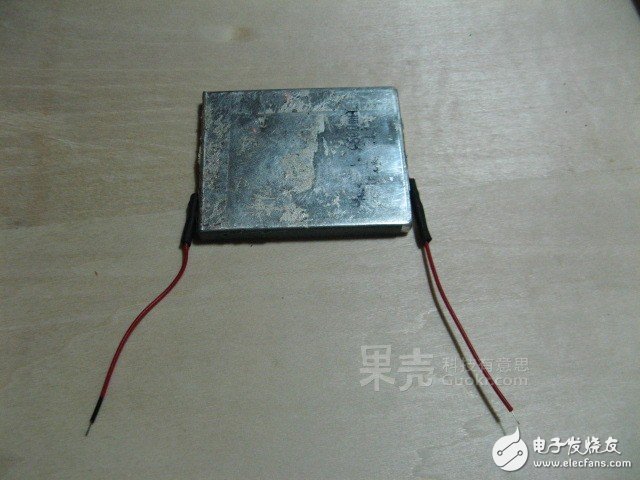
First, lead the wire at the positive and negative poles of the battery, pay attention to distinguish between positive and negative poles and avoid short circuit!
Since the author of this production can't find the thin flying thread of different colors for the time being, the ancient method of marking the black negative lead pen with the mark is used to distinguish the positive and negative poles...
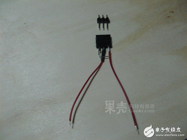
Since there are no other small enough and suitable power plug connectors, only the pin headers are used instead.
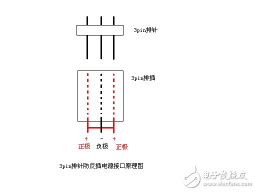
Why use three pin headers? The reason is to prevent reverse connection, the principle is shown in the figure. If this is the case, no matter whether it is inserted or reversed, it will not cause other accidents due to the wrong positive and negative poles.
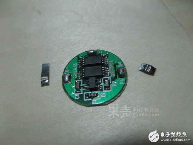
This is a protective circuit board that was removed from the old 16340 lithium battery used in the flashlight. The original nickel piece was first welded.
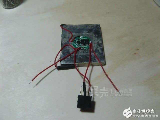
Connect the battery to the protection circuit and connect the charging interface to the protection circuit. Pay attention to the power cord of the two Bluetooth modules.
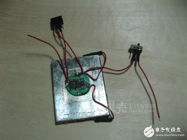
Remember to install the power switch on the power cord of the Bluetooth module!
Strip the earphone cords in the earpieces on the left and right sides to expose the inner core.
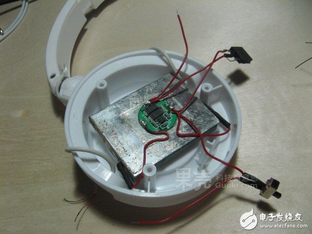
The battery is glued to the inside of the left earpiece with hot melt adhesive. Pay attention to the position and direction.
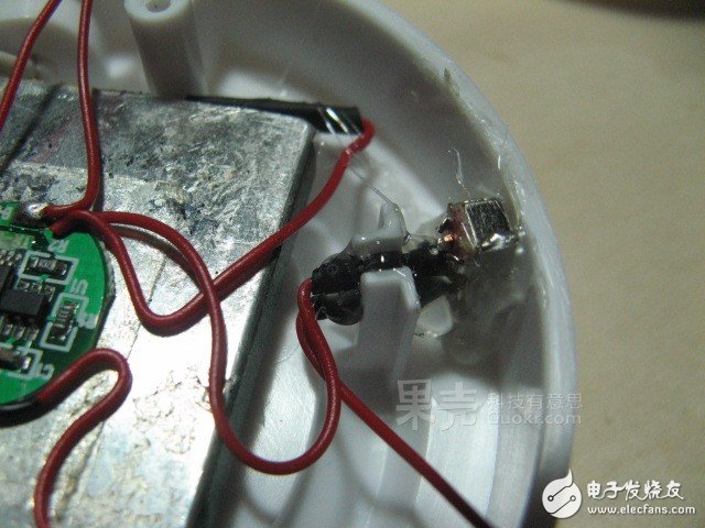
The power switch is just placed at the entrance of the previous headphone cable and then secured with hot melt adhesive.
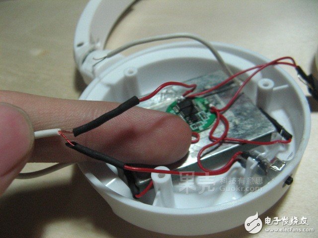
Solder the originally reserved Bluetooth module power cord with two enameled wires in one of the earphone cords. Note that the enameled wire needs to be burned with a lighter to burn off the surface of the paint layer!
Remember to write on the paper which headphone cable is the power source and which one is the left channel!
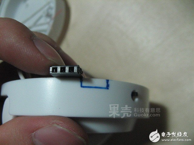
----------------------
How to easily overcome the quality problems of 4G product design? LTE test helps you!

As for the power interface, you need to make a suitable slot yourself.
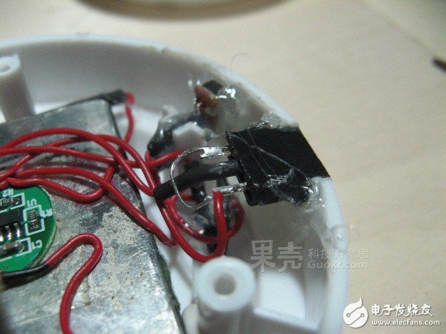
Remember to polish it after opening the groove, then fix it with hot melt adhesive.
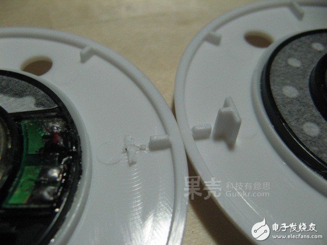
Since the position of the power connector is just a card position on the speaker unit, as shown in the figure, only the card position can be cut off to properly mount the speaker unit.
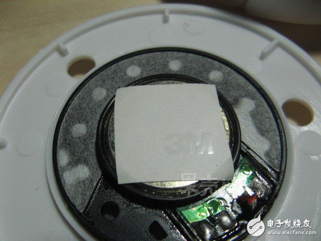
Remember to put a piece of insulating tape on the back of the speaker to prevent the metal casing from causing a short circuit on the battery protection board.
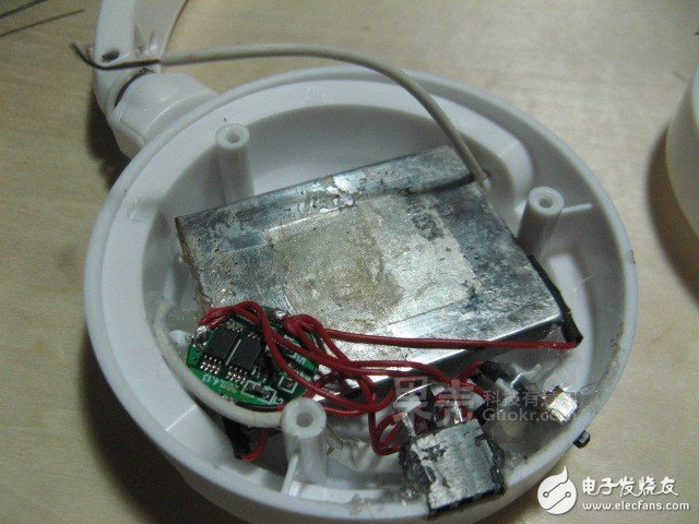
Later, I found that the battery protection board needs to be moved to the side to be able to properly install the speaker unit, otherwise the protection board just can't fit the back of the speaker...
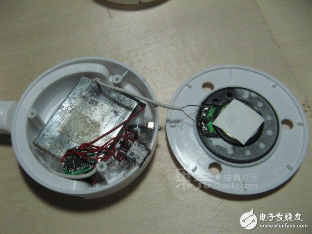
Solder the other headphone wire to the speaker module and prepare the final left earpiece.
Remind me to take the pen and paper to record which headphone cable is the left channel which is the power supply!
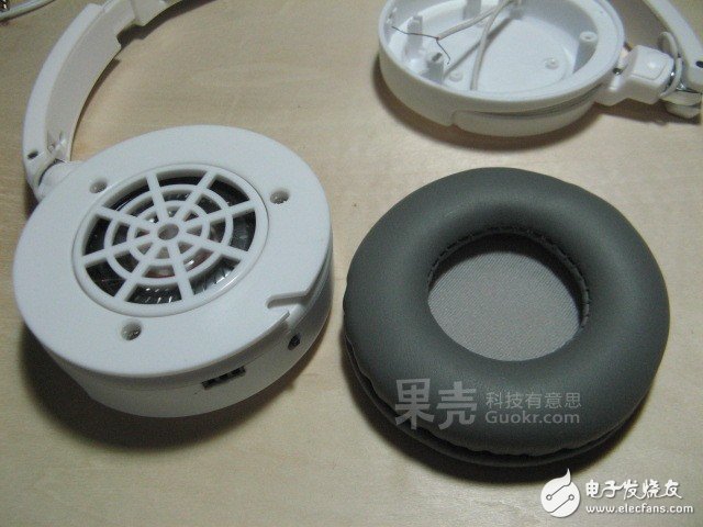
With three screws and earmuffs, the headset is half done!
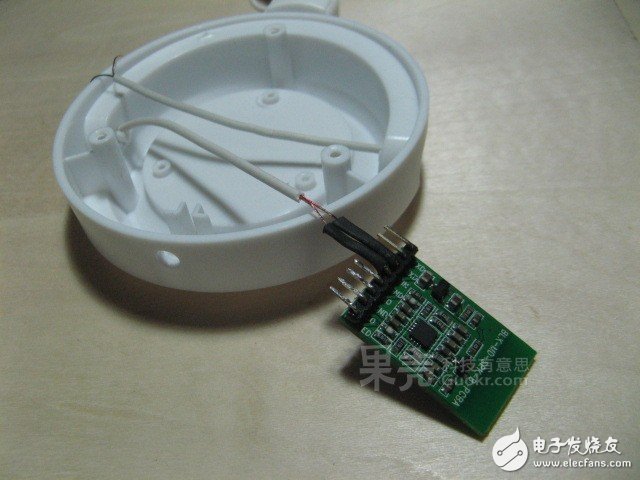
Take out the previous record and solder the power cable to the Bluetooth module. Note that both the enameled wire and the Bluetooth module are relatively fragile, and must be gentle when soldering~
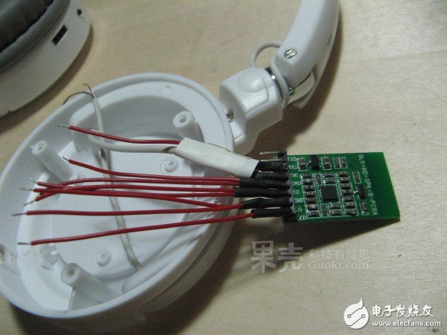
Then pick up the required wiring on the Bluetooth module. I am here with one indicator light, two left and right channels and two audio ground lines.
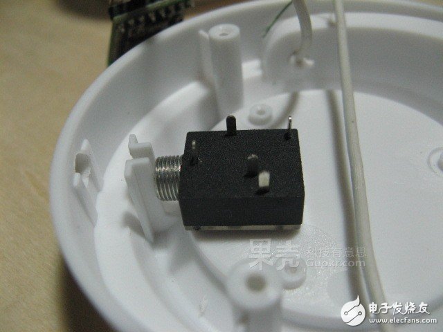
Ready to install the audio input/output interface. For aesthetic reasons, it is also installed at the entrance of the original headphone cable, but this time you need to ream and cut the card.
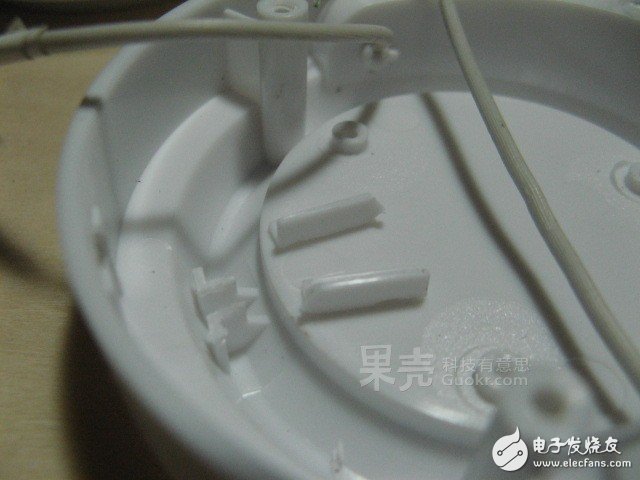
Cut the card and then ream.
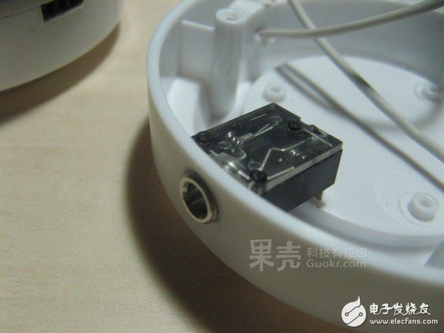
The 3.5mm audio socket is perfectly placed!
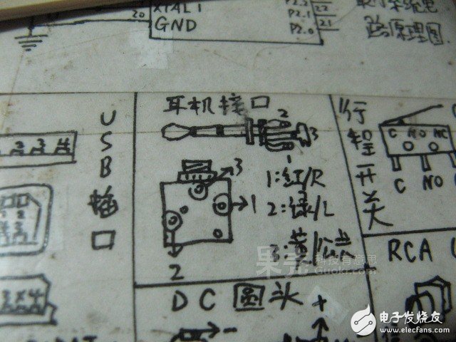
Attach a list of common wiring definitions attached to the table on the second day of the second day...
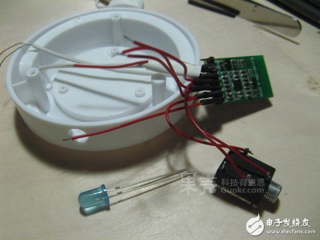
Connect the audio input/output interface and prepare to connect the indicator light.
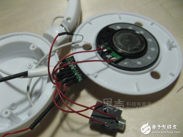
Solder the right channel section to the speaker unit.
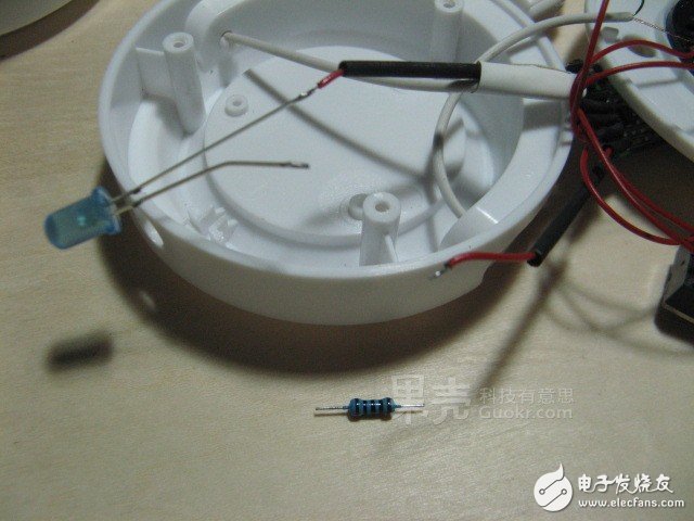
The LED status indicator requires a resistance of about 1K in series to avoid excessive brightness.
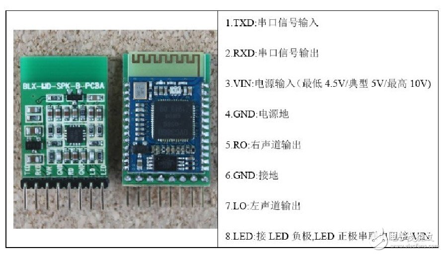
Bluetooth module wiring diagram
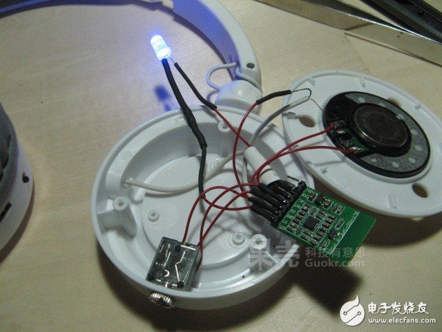
Connect the right channel audio cable that will pass through the left side, then turn on the power switch test, the blue light flashes quickly, and the normal search is entered!
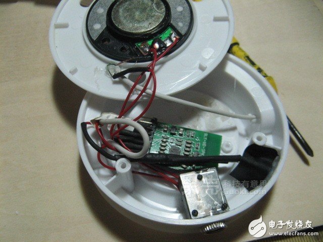
The LED is glued to the earpiece casing with a hot melt adhesive. It is best to apply a layer of black insulating tape to prevent light leakage.
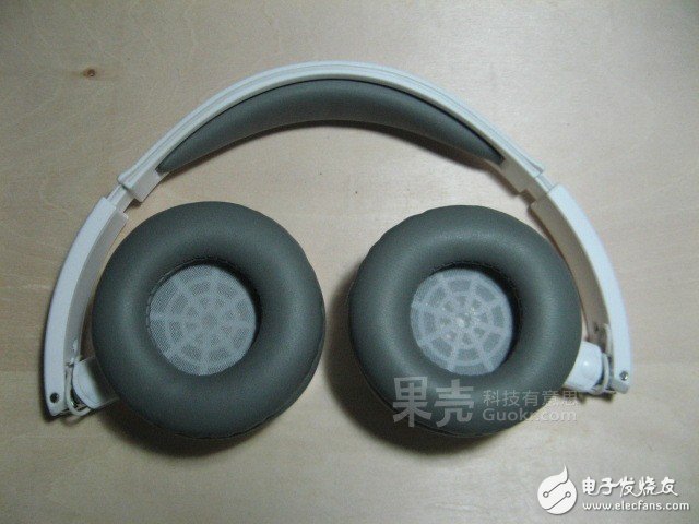
The right earpiece is also installed, and a Bluetooth headset that you created yourself is now finished!
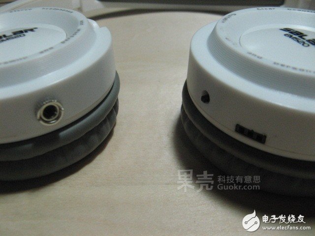
Simple and beautiful interface and switch.
----------------------
How to easily overcome the quality problems of 4G product design? LTE test helps you!

Charging part production
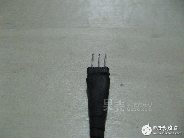
First, make the charging pin in the same way as the charging socket (the schematic is the same as the wiring of the pin and the plug).
 ?
?
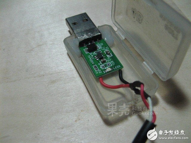
Then connect the battery terminal of a lithium battery charging board to the completed charging line.
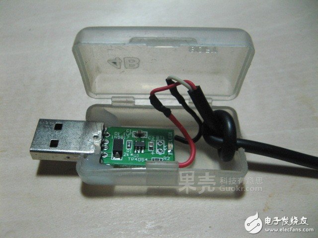
To avoid tearing the wire or dropping the solder joint, it is best to make a hole in the line and then pull it out of the box.
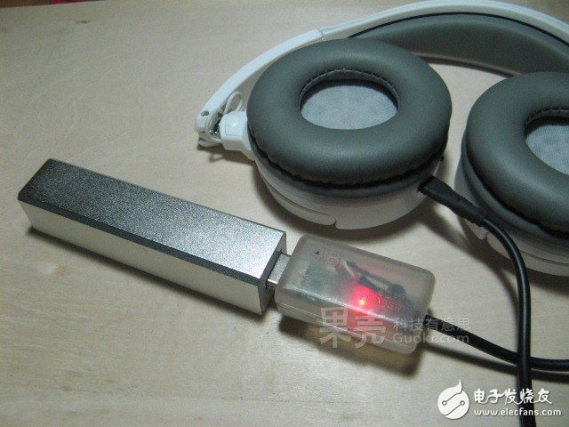
Close the lid, plug in and start adding energy to your Bluetooth headset!
----------------------
How to easily overcome the quality problems of 4G product design? LTE test helps you!

The low voltage inverter produced by FGI covers every automation application requirement in the industrial plant. This Low Voltage Converter is mainly used for controlling and adjusting the speed and torque of three-phase AC asynchronous motors. Using the latest technological advancements in AC motor speed control, the FGI high performance Low Voltage Drives meet the needs of smart machines by increasing system reliability, improving process control and minimizing total installed project costs.
Low Voltage Drives
Low Voltage Drives,Low Voltage Vfd,Low Voltage Ac Drive,Low Voltage Inverters,Low Voltage Converter,Low Voltage Boost Converter
FGI SCIENCE AND TECHNOLOGY CO., LTD , https://www.fgi-tech.com