The simplest probe is a wire that connects the circuit under test to the input of an electronic oscilloscope. The complex probe consists of a RC component and an active device. A simple probe does not take shielding measures and is easily interfered by external electromagnetic fields, and its own equivalent capacitance is large, causing the load of the circuit under test to increase, and the signal to be measured is distorted.
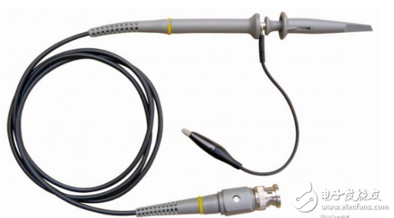
1. The probes are generally packaged in two, because the current oscilloscopes are more than two channels. In order to distinguish the probes when the two channels are simultaneously measured, the color calibration is performed on each probe, such as the color circle.
2. Get the probe, first calibrate, what kind of probe needs standard? Calibration is required except for the non-attenuating probe (1:1). Calibration is the first time the probe must be calibrated when used with an oscilloscope. It must be calibrated when measuring different oscilloscopes.
3. After the calibration, the probe can enter the measurement. When measuring, please note that if you do not know the voltage of the circuit under test, select the probe attenuation position as much as possible to prevent the high voltage from damaging the oscilloscope.
4. When testing high-impedance circuits such as crystal oscillators, that is, when the circuit has an influence on the measured load, select the probe attenuation gear position measurement, because the impedance of the attenuation gear position is very high, generally 10:1 probe is 10MΩ, 100: The probe of 1 is 100 MΩ.
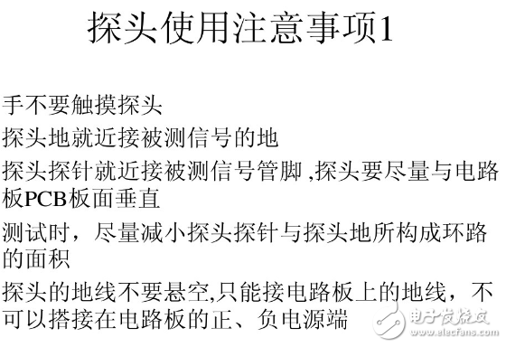
5. When testing the circuit, make sure that the grounding wire of the probe is grounded reliably, especially when the high voltage probe is not high voltage. The grounding position of the grounding wire will also affect the measurement accuracy.
6. There are electronic components inside the probe, so there are also pressure resistance parameters, which can not exceed the withstand voltage value, otherwise it will not only damage the probe, but also directly damage the oscilloscope.
7. The bandwidth of the probe, the high frequency probe can be compatible with low frequency, but the high frequency can not be tested at low frequency. When selecting the probe, try to choose the bandwidth larger than the oscilloscope.
8. The probe test should select the attenuation file as much as possible, and the attenuation file has circuit compensation to ensure the measurement waveform distortion is small and the reduction degree is high.
9. There is a test hook at the front end of the probe. For convenience, the test hook is directly measured by the hook circuit. This will affect the test accuracy, especially in the case of low voltage and high frequency, because the test hook is not shielded. The interference is great.
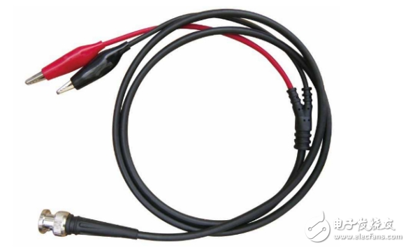
1. The probe has a ground wire and a signal wire. The ground wire is the one that is connected to the oscilloscope input terminal casing. It is generally clip-shaped. The signal wire usually has a probe hook. If you connect, you can connect the oscilloscope ground wire to you. Ground the device, connect the signal line terminal to your signal terminal. Note that if the signal to be measured is not isolated from the mains, it cannot be directly measured.
2. The black clip of the probe line passes through the metal mesh shield line of the measuring line. The measured signal that is shielded from entering the oscilloscope is not disturbed, and is also the 0-level line of the measured signal. Therefore, it must be clamped at the 0 level corresponding to the measured signal, and the red clip is clamped at the corresponding point of the signal under test. Commonly used black clip pinch points are: 0 level, 0 potential, ground line, etc.
1, the first is the bandwidth, this will usually be written on the probe, how many MHz. If the probe's bandwidth is not enough, the oscilloscope's bandwidth is high, it is useless, bottleneck effect.
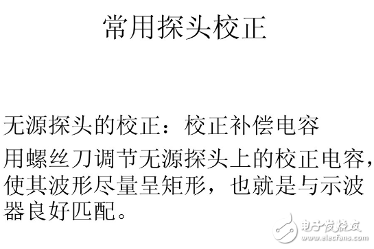
2. The other is the impedance matching of the probe. The probe should be adjusted to its impedance matching section before use. Usually there is a tunable capacitor on the probe near the end of the oscilloscope, and some probes have tunable capacitors near the end of the probe. They are used to adjust the impedance matching of the oscilloscope probe. If the impedance does not match, the measured waveform will be distorted. To adjust the oscilloscope probe impedance matching, first place the oscilloscope's input selection on GND, then adjust the Y-axis displacement knob so that the scan line appears in the middle of the oscilloscope. Check if the scan line is horizontal (ie, it coincides with the horizontal center line of the oscilloscope). If not, you need to adjust the horizontal balance knob (usually the analog oscilloscope has this adjustment terminal. In the small hole, you need to use a screwdriver to adjust it. The oscilloscope does not require adjustment). Then, the oscilloscope's input selection is connected to the DC coupling, and the oscilloscope probe is connected to the oscilloscope's test signal output (usually the oscilloscope has this output terminal, usually a 1KHz square wave signal), and then adjust the scan time. The knob allows the waveform to be displayed for about 2 cycles. Adjust the Y-axis gain knob so that the peak-to-peak value of the waveform is around 1/2 of the screen width. Then observe the upper and lower sides of the square wave to see if it is level. If overshoot, tilt, etc. occur, the matching capacitor on the probe needs to be adjusted. Adjust it with a small screwdriver until the waveforms on the top and bottom are horizontal and there is no overshoot. Of course, due to the quality of the oscilloscope probe, there may be no distortion-free effect, and only the best results can be achieved.
3. In addition, there is a small switch on the oscilloscope probe that selects the range: X10 and X1. When the X1 file is selected, the signal is not attenuated into the oscilloscope. When X10 is selected, the signal is attenuated to 1/10 and then to the oscilloscope. Therefore, when using the oscilloscope's X10 file, you should increase the reading on the oscilloscope by 10 times (some oscilloscopes, you can select the X10 file on the oscilloscope side to match the probe, so that after the oscilloscope side is also set to the X10 file, the direct reading is can). When we want to measure a higher voltage, we can use the X10 function of the probe to attenuate the higher voltage and enter the oscilloscope. In addition, the input impedance of the X10 file is much higher than that of the X1 file, so when testing the signal waveform with weak drive capability, it is better to measure the probe to the X10 file. However, it should be noted that when the signal voltage is not clear, you should first use the X10 file to check that the voltage is not too high and then use the correct range measurement. It is necessary to develop such a habit, otherwise, which Because Tian Wanyi has damaged the oscilloscope in this way, it is too late to regret it. I often ask questions, why can't I see the waveform on the crystal pin with an oscilloscope? One possible reason is that the X1 file of the probe is used, which is equivalent to a very heavy load (an oscilloscope probe uses &TImes; a gear with hundreds of pF in the first gear) is connected in parallel in the crystal circuit, causing the circuit to stop. . The correct method should be to use the probe's X10 file. This should be noted in the use, even if you do not stop vibration, it is possible to see the real waveform due to excessive changes in the oscillation conditions.
4. When the oscilloscope probe is in use, make sure that the ground wire clip is reliably grounded (the ground of the system under test, not the real earth). Otherwise, when measuring, you will see a large 50Hz signal. This is because The ground line of the oscilloscope is not connected, but it is generated by sensing the 50Hz power frequency mains in the space. If you find a very strong 50Hz signal on the oscilloscope (China's mains frequency is 50Hz, foreign 60Hz), then you should pay attention to see if the probe's ground wire is not connected. Due to the frequent use of oscilloscope probes, grounding may be broken. The detection method is: adjust the oscilloscope to the appropriate scanning frequency and Y-axis gain, then touch the probe in the middle of the probe by hand, then you should be able to see the waveform, usually a 50Hz signal. If there is no waveform at this time, you can check if the signal line in the middle of the probe is damaged. Then, clip the ground clamp of the oscilloscope probe to the probe (or the hook) of the probe, and then touch the probe of the probe by hand. At this time, you should not see the signal (or the amplitude is very weak). The ground wire of the probe is good, otherwise the ground wire is damaged. Usually the line connecting the clips is broken, usually re-welding, and can be replaced if necessary. Note that the grounding of the connecting clips should not be too long, otherwise it is easy to introduce interference, especially in high-frequency small-signal environments. The ground clamp of the oscilloscope probe should be close to the measurement point, especially when measuring signals with higher frequency and smaller amplitude. Because of the long ground wire, a ring is formed, which is like a coil that senses the electromagnetic field of the space. In addition, when the current in the ground line in the system is large, a voltage drop will also occur on the ground line, so the ground wire of the oscilloscope probe should be connected to the ground near the point to be tested.
Provide you with the supply of pulse oximeter finger. to help you safely get back to your daily routine.
With more than 15+ yrs rich MFG experience, you can definitely trust in and cooperate with.
Our strict quality control protocol thoroughly vets every aspect of production, storage, and shipments all the way way to our end customers.
Our products include pulse Oximeter Finger, Forehead Thermometer, Automatic foam soap dispenser, etc.
Pulse Oximeter Manufacturers, oxygen saturation, oximetry
TOPNOTCH INTERNATIONAL GROUP LIMITED , https://www.itopnoobluetoothes.com