â— Understand the particularity of AC power supply
â—Understand PF and THD
â—PPFC principle and implementation ideas
â—APFC principle and implementation ideas
Understand the particularity of AC power supplyUnderstand the model of power supply plant and power equipment
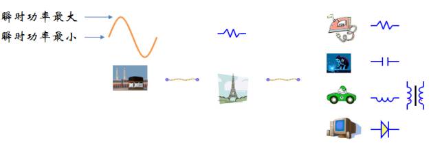
â— The power supply plant provides AC power, that is, the energy provided by the power supply plant exhibits a sinusoidal form of fluctuation, rather than constant power.
â— The transmission line between the power plant and the consumer equipment is electrically resistive, and these resistors consume energy.
â— Electrical equipment is resistive, capacitive and inductive.
Equivalent circuit of equipment of various load types

Various load conditions
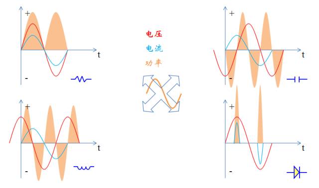
â—The figure below shows the energy consumption of the four types of loads.
Detailed analysis of various load conditions (resistance vs sensing)
â— As can be seen from the previous figure, the power consumed = U * I, the resistance is always positive, while the capacitance and inductance are not, one will be positive, one will be negative, that is, the inductor and capacitor will be Taking energy from the power plant will provide energy to the power plant.
★ The reason for this phenomenon is that the inductor and capacitor belong to the energy storage device and do not consume energy by itself.
â— In this process of energy storage and discharge, energy is consumed on the power supply line. Since the power supply equipment does not consume energy, the power supply plant cannot charge the electricity fee, but the power supply plant still needs to set up the corresponding power supply equipment, and does not stop. Providing energy.

Detailed analysis of various load conditions (in the case of diodes)
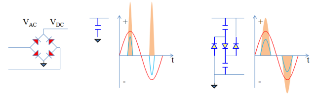
â— The rectifier circuit formed by the diode, plus the capacitor, is used to generate the DC output. This is a very common structure. Only when the AC voltage is higher than the capacitor voltage, the diode can be turned on. At this time, there is current, in order to provide the whole. The power of the cycle, in this range must have a large current, that is, the AC source must provide energy for a very long time to the device in a short period of time.
★ Since the power supply plant can only produce sinusoidal power output, in order to achieve this goal, the power supply plant must build power supply equipment far beyond normal consumption to maintain the power consumption of the electrical equipment.

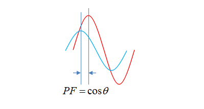
In order to describe the case where the current and voltage are not synchronized due to such a capacitive inductance, a definition of the power factor is introduced.
• Use the cosine of the difference between the phase angles of current and voltage as the power factor.
★ Is PF bigger or smaller?
Total harmonic distortion (THD)
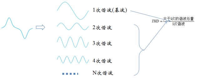
â— A non-sinusoidal periodic waveform can be split into Fourier series, thus obtaining the fundamental and harmonics of the periodic waveform.
â— Total harmonic distortion is used to indicate the size of each harmonic. In the field of power supply, the magnitude of the harmonics refers to the size of the stream.
★ THD is bigger or smaller.
Hazard of harmonic distortion
â— The current waveform generated by the power supply plant is the sine of the fundamental wave, and the waveforms of other higher harmonics cannot be generated by the power supply plant. Therefore, the power supply plant must use extra force to generate all the higher harmonics, so THD actually Describes the additional power supply capacity that the power supply plant must have, or the invalid work done.
â— Other hazards of harmonic distortion are also manifested in the generation of high-frequency signals that interfere with other devices. This interference can be transmitted through the line or through radiation. The line conduction is called RFI and the radiation propagation is called EMI.
Specific calculation of total harmonic distortion
â— Harmonic distortion describes a bunch of sinusoidal signals, or AC signals. AC signals are rms values, so they must be calculated using squares and roots. The formula is as follows:
★ The first step is to find the ratio of each higher harmonic to the fundamental wave;
★ The second step, the ratio is summed, in theory, H can be infinite, but in practical applications, H will not take a large amount, generally tens of is accurate enough;
★ The third step, prescribing.

Graphical representation of harmonic distortion
â— Total harmonic distortion represents a waste of power supply capability, while the amplitude of higher harmonics represents the intensity of electromagnetic interference. Therefore, icons are often used to represent harmonic distortion, so that harmonic distortion can be seen in comparison. The degree of electromagnetic interference hazard.
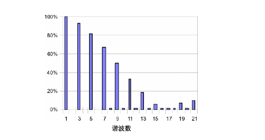
Even harmonics and odd harmonics
â— Careful observation reveals that on the current harmonic distortion map, the component of the even harmonic is almost zero.
â— This is not accidental. In the field of power, when it comes to harmonic distortion, there is no need to consider even harmonics. Only odd harmonics are considered, because even harmonic components can be ignored.
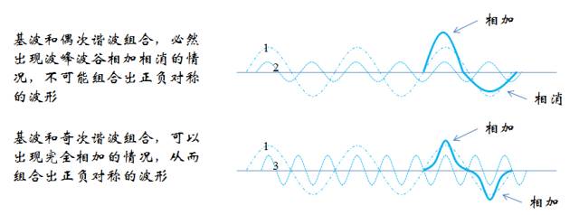
The reason why the even harmonic component is 0 is that the current waveform always exhibits a form of positive and negative symmetry. This symmetrical waveform is called an odd harmonic shape, and its even component is 0. The analysis is as follows:
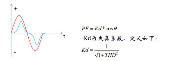
Consider PF after THD
â— In real applications, devices often contain capacitors/inductors and active devices. Therefore, the current waveform exhibits a phase difference from the voltage sinusoid and exhibits non-sinusoidal characteristics. As shown in the following figure, the power factor is defined as:
summary
â— It can be seen now that the friendliness of the electrical equipment can be measured by PF. In many cases, PF and THD are related. The larger the THD, the lower the PF, but the small THD does not mean that the PF is high, but also the current. The effect of the phase.
â— THD should be small, and the harmonic components at high frequencies should be as small as possible to reduce interference.
PPFC principle and implementation ideasâ— There are two reasons for the low PF, the current phase shift caused by the capacitor or the inductor, and the waveform distortion caused by the active device.
◠The circuit that raises PF is called PFC circuit, and the idea of ​​PFC is also divided into two:
★ Add compensation circuit, such as load is capacitor, add inductance on the power supply line, this method is called passive PFC, often used in the case of phase shift only;
★ For switching power supplies, the main problem is waveform distortion, so passive PFC cannot be used. Only other methods can be used. These methods are collectively referred to as active PFC.
-- Active PFC is also divided into two types, one is PPFC (Passive PFC), and the other is APFC (Active PFC).
- Sometimes, the passive PFC is also classified as passive, so that the PFC is divided into two types, P and A. P includes both passive and active.
PPFC circuit
• A structure called a flow-by-flow circuit can be used to increase the PF value of the switching power supply.
★ Pay attention to the connection of the flow-by-flow circuit. When the VDC is higher than the two capacitor voltages, the flow-by-flow circuit is charged. When the voltage of the VDC is lower than the parallel voltage of the two capacitors, the current-by-flow circuit discharges when the VDC is between the two. The flow-by-flow circuit neither discharges nor charges.
★The two capacitors are identical, so the voltage of the capacitor will always be equal.
Method for increasing PF value by flow-by-flow circuit
â— If there is no flow-by-flow circuit, when VAC
★Assuming VAC is 220V and VDC is stable at 200V, then when there is no flow-by-flow circuit, only VAC>200V, the diode will be turned on. When there is a flow-by-flow circuit, VAC>100V, the diode will be turned on.
Superposition of flow-by-flow circuits
â— From the previous analysis, it can be seen that the flow-by-flow circuit is looped through the diode, so that the capacitors are charged in series, parallel discharge, and the number in series is 2, so the voltage drop in the charge and discharge interval is 2 times.
â— If you want to improve the PFC effect of the flow-by-flow circuit, you can increase the voltage drop to 3 or even 4.

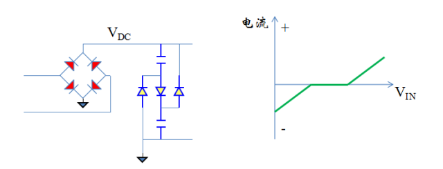
Principle of APFC
â— The culprit of the waveform distortion of the switching power supply is the capacitance behind the rectifier bridge. This problem can be alleviated by using the flow-by-flow circuit, but it cannot be eradicated, and the active PFC can eradicate this problem.
â— The active PFC method is to directly remove the capacitor behind the rectifier bridge and let the input current continue.
★ Light does not last enough. The part behind the rectifier bridge must also look like a resistor, so that the current changes with the input voltage.
★Because the switching power supply is an inductive load behind the rectifier bridge, the current-voltage relationship of the inductor is:

★ So the switching power supply needs to control t to make ʃvdt proportional to V.

Form of APFC
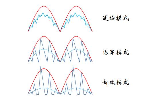
â— The switching power supply intermittently transfers energy through switching, so it is impossible to make the instantaneous current appear as a continuous smooth sinusoidal waveform, and only the average current waveform can be sinusoidal.
★ There are 3 types of current waveforms, corresponding to 3 modes CCM, BCM (CRM), DCM.
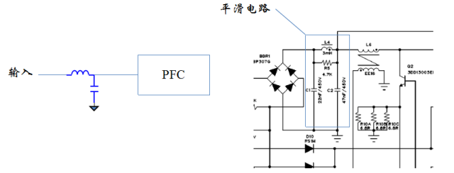
Current smoothing
â— The switching power supply can only produce a sawtooth current, while the PFC requires a smoother current, otherwise the current THD will be large. Therefore, a current low-pass filter circuit needs to be added to the input terminal.
★ Current filtering uses inductors and capacitors. The inductor smoothes the current, while the capacitor stores energy to cope with sudden changes in current during PFC.
Comparison of 3 modes
â— These three modes, the essential difference is the current flowing through the inductor.
★ CCM, the inductor current is continuous;
★ BCM, the inductor current is not continuous, but will not last for 0;
★ DCM, the inductor current has a duration of 0.
â— From the power source: CCM > BCM > DCM.
★ Theoretically, high power can also be used for low power, but the control loop of CCM has huge defects and cannot achieve high switching frequency. Therefore, CCM is usually not used in small power segments.

BCM implementation method
â— To make the average current of the BCM sinusoidal, two conditions are required:
★ The peak envelope of the current flowing through the inductor is sinusoidal;
★ The input average current is proportional to the peak inductance.
â— For the second condition, except for boost, other topologies can't do it, as shown in the following figure:
★Boost topology has input current in the whole cycle, and the average current is exactly 1/2 of the envelope current. For other topologies, only the input current is available in the TON time, and the input current is 0 in the Toff time. The average current and peak current are not a fixed proportional relationship.

Boost method of implementing BCM
â— The circuit needs to obtain 2 time points, the end of the current cycle TON and the current cycle TOFF end.
★ The TON end of the current cycle is detected by the current peak comparator, and the end of TOFF is detected by the zero crossing comparator.
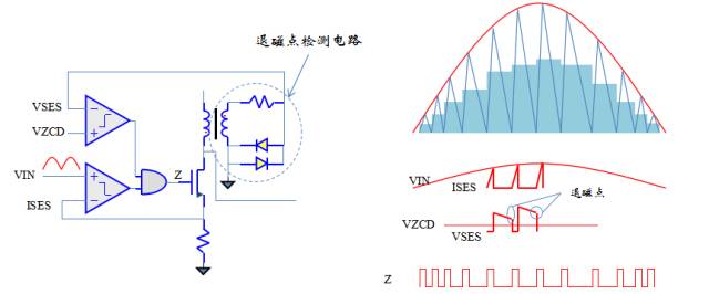
On-time problem
â— Careful observation of BCM, you can see that the conduction time seems to be constant, this is not intentionally drawn, but for a reason
â— The current on the inductor can be expressed by the following formula:

â— This formula shows that the current on the inductor rises linearly, the slope of the rise depends on the input voltage, and the end point of the rise also depends on the input voltage, which causes the on-time to be finally independent of the input voltage.

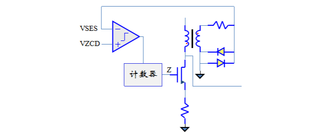
Improvements in the PFC method - fixed on-time
â— According to the previous analysis, after Boost realizes PFC, the on-time becomes constant. In turn, the on-time is set to be constant as soon as it comes up. Is it possible to implement PFC? The answer is yes.
★ After the improvement, it becomes the active fixed on-time, thus eliminating the peak current comparison circuit.
★ Fixed on-time is currently the most popular PFC technology. It is suitable for digital control. The counter generates a positive pulse of fixed width. Each time the zero-crossing comparator detects the demagnetization point, it generates a positive pulse.
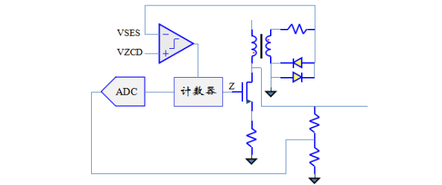
Method for adjusting output voltage of PFC power supply
â— Many power supplies have the need for voltage regulation. The so-called voltage regulation is actually adjusting the energy transmitted by the power supply. For a fixed on-time, adjusting the envelope of the peak current can adjust the average current and adjust the input power. The output voltage is then adjusted.
★ Because the input voltage is AC, it is always constant, so the current slope on the inductor is constant. After scaling the envelope, it is equivalent to changing the threshold of the peak current comparator. The current triangle on the inductor will change, envelope. The shorter the line, the smaller the average current, the lower the output power, the shorter the TON time, and the higher the switching frequency of the switch.

Output voltage regulation method
â— From the previous analysis, it is known that to adjust the output voltage, only TON needs to be adjusted. Therefore, the output voltage is fed back and the TON can be adjusted.
BCM issues and solutions
â— The characteristic of BCM is that the lower the output power, the higher the switching frequency. If the power supply itself needs to be switched within a large output power, such as dimming, it needs to be switched within 1%-100%, and the switching frequency of the switching tube also needs to be switched. Close to 100 times the range of variation.
★ Such a large range of variation is impossible to achieve, no matter MOS or inductance, it is impossible to maintain an optimal working state at such a large switching frequency.
The solution is to insert a dead zone wait time in each cycle to turn the BCM into DCM mode.
Join the dead zone waiting DCM
â— If you need to reduce the input current, you can not adjust TON, but increase the waiting time after each switching cycle. The more the input current decreases, the longer the waiting time. The lower the input current is, the lower the frequency is when TON is unchanged. .
★ If the adjustment range is not large, it is enough to join the dead zone. If the adjustment range is large, you can combine the dead zone waiting and the envelope adjustment, or one for the main and the other for the auxiliary, such as the envelope. The main, dead zone waiting is supplemented, or two techniques are used to achieve finer adjustments.
-- In the digital control mode, the minimum adjustment granularity of TON is 1 TCLK , and after the dead zone wait (compensation) is introduced, the minimum adjustment granularity can be higher than one TCLK .

Voltage stabilization algorithm combined with dead zone waiting
â— After adjusting T ON and T DEAD at the same time , the control algorithm becomes complicated. One algorithm is as follows:
★ mainly by T ON to adjust the output power, T ON by adjusting the height of the envelope, T DEAD exist entirely in order to adjust the frequency, thus obtaining two methods:
-- First adjust T ON , T ON can not adjust T DEAD , or adjust T DEAD first , then T ON ;
-- First adjust T ON , T ON can not adjust T DEAD , or adjust T DEAD first , then T ON ;

Compare several algorithms
â— In terms of development difficulty, it is more simple to adjust one parameter at a time than to adjust multiple parameters at a time, but multiple parameters can be implemented at one time to implement a richer algorithm. For example, weighting parameters can achieve different curve effects, and even Switch the frequency from start to finish.
★ Note that the curves of the two parameters are always different trends, T ON increases, the switching frequency decreases, and T DEAD decreases, the switching frequency increases, so the switching frequency can be theoretically unchanged.

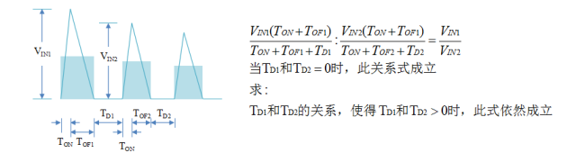
Multi-period equilibrium relationship of dead time
â— In the case of BCM, the average current is naturally sinusoidal, and after the dead zone is introduced, it becomes DCM, and the average current can no longer be naturally sinusoidal. At this time, a digital algorithm is needed to equalize the T DEAD of each cycle , so that the average current remains. Can maintain a sinusoidal shape.
★ The so-called equilibrium means that T DEAD inserted into each cycle maintains a certain relationship.
â— The development of the equalization algorithm is as follows:
Expand to other topologies
â— As analyzed earlier, the advantage of Boost over other topologies is that both T ON and T ON have input current, but after the dead time is introduced, T DEAD still has no current. At this time, Boost has no advantage over other topologies. So any topology can be used to implement PFC.
â— Assuming that the fixed on-time is still used, the development of the T DEAD equalization algorithm for other topologies is as follows:

PFC and constant current conflict
â— In the front, the output power is adjusted by adjusting the output voltage. However, in many applications, the output power is adjusted by adjusting the output current, which brings a big problem to the PFC.
★ The biggest difference between voltage regulation and steady current is that the voltage regulation only needs to ensure that the average output voltage is constant for a long time, and the current steady current technology needs to keep the current constant for each switching cycle.
-- Why can the voltage be viewed for a period of time? Because the load has a large capacitance, the voltage on this capacitor is the average voltage over a period of time. By feeding this voltage sample back to the input, the average voltage can be adjusted.
- The current is not good. There is currently no way to change the current per cycle, and the average current remains constant for a period of time because there is no way to sample the average current over a period of time.
â— PFC requires the current to be sinusoidal, that is, each cycle is different, and the constant current requires the current to be the same every cycle, thus forming a pair of irreconcilable contradictions.
Solve the conflict between PFC and constant current
â— At present, there is no good way to improve PF and constant current accuracy at the same time. Several known methods are as follows:
★ Sampling 2 level scheme, the first level is Boost, the high level is achieved, and the second level is constant current, thus avoiding the conflict between the two, but the disadvantage is high cost;
★ Using the method of splitting cycle, divide one AC cycle into multiple time segments, do PFC for some time, and do constant current for other time, as shown in the following figure, this can be achieved in single level, but the effect is worse than that of 2 Some more.
• For high-power, cost-insensitive applications, a two-stage solution is appropriate, but for cost-sensitive situations, significant effort is required to optimize.

Cat7 Patch Cord,Patch Cable Cat 7,Cat 7 Patch Cable,Patch Cord Cat7
CIXI LANGUANG PHOTOELECTRIC TECHNOLOGY CO..LTD , https://www.cxblueray.com