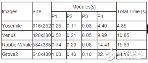
The optical flow algorithm used in this project is based on the model of Horn-Schunck [5]. Compared with the Lucas- Kanade [2] optical flow algorithm, the calculated optical flow is more dense and accurate to each pixel; The need to solve the Euler-Lagrange equation requires a large number of iterations, so the time to calculate the optical flow is quite time consuming. For example, processing a 640x480 image sequence on a single-core ARM on Zedboard requires 24.14s to complete, which indicates that in the traditional single It is difficult to meet the requirements of real-time calculation of optical flow field on the embedded platform of the architecture.
1. Optical flow algorithm based on Horn-Schunck model1.1 Optical flow constraints The optical flow 15wx铌?ux, vx, ht)"> assumes that the image sequence is at a certain pixel point at time t 15t"> with this at time 15t+1"> t+1 The offset of a pixel is 15 (x+u, y+v)"> remains unchanged, ie. This is the assumption of conservation of gray values. By Taylor expansion, the constraint of optical flow (OFC) can be obtained: where the subscript represents the gradient of the image.
1.2 Horn-Schunck Model
In 1981, Horn and Schunck proposed an additional constraint to convert the overall smooth constraint of the optical flow field into a variational problem based on the continuous and smooth characteristics of the optical flow field of the same moving object. Its energy equation is as follows:
The data item represents the gray value conservation constraint, and the smooth term represents the optical flow smoothing constraint.
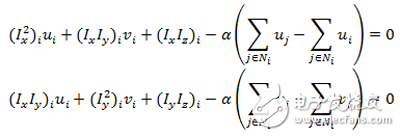
1.3 Euler-Lagrange equation According to the Horn-Schunck energy equation, the discrete Euler-Lagrangian equation can be derived as follows:

Wherein, the coordinates representing the pixel points of the image represent adjacent pixels in the four directions of up, down, left, and right of one pixel, and of course, there are fewer than four elements at the boundary of the image.
1.4 Super Relaxation Iteration (SOR)
According to the Euler-Lagrange equation above, it is not difficult to push out the iterative equation. Here, the fastest relaxation algorithm (SOR) with the fastest convergence rate is selected. The initial value of the optical flow is that the iterative equation is as follows:

Where w is the iterative weighting factor, k is the number of iterations, is the calculated weight of the optical flow, represents the upper and left adjacent pixel points of the first pixel, and represents the lower and right phases of the first pixel Neighboring pixels.
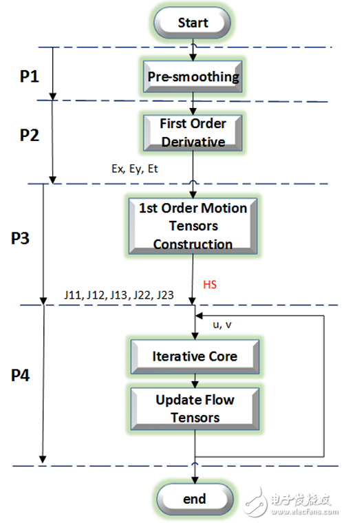
2 Workflow introductionAccording to the above theoretical analysis, the calculation of optical flow method can be divided into four stages: preprocessing stage (P1), gradient calculation stage (P2), motion model construction stage (P3) and iterative stage (P5), as shown in Fig. 2. Shown.
2.1 Preprocessing stage (P1)
This phase is a sequence of smoothed images that are used to reduce image noise and external effects, usually with convolution. This stage is a general purpose image operation.
2.2 Gradient calculation phase (P2)
This stage is used to calculate the gradient of a smooth image, including horizontal gradients, vertical gradients, and time gradients. Calculating the gradient is usually also done by convolution.
2.3 Motion Model Construction Phase (P3)
This stage is to construct the information of the motion model based on the calculated gradient. According to the super-relaxation formula, information that needs to construct five motion models, namely J11, J12, J13, J22, J23, can be derived. Its operation is matrix multiplication.
2.4 Iteration phase (P4)
This stage is the result of calculating the optical flow by the super-relaxation algorithm. After each iteration, the information of the optical flow needs to be updated once, and then the next iteration is performed as the initial value. The operation at this stage is based on an iterative formula.

2.3 Software execution time
The experimental platform of the software was tested on the ARM Cortex-A9 processor on Zedboard, including two 32KB L1 caches and 512KB shared L2 cache, and 512MB of memory space. The test set was downloaded from. The Horn-Schunck optical flow algorithm is implemented in ANSI C. The number of iterations is set to 100 times.
The execution time of the dense optical flow method based on the Horn-Schunck model in software is shown in Table 1. It is not difficult to find that as the image grows larger, the required execution time increases continuously; the iterative part (P4) accounts for To a large proportion of time.

Engineering Ceramics,Ceramics Used In Engineering,Ceramics In Mechanical Engineering,Engineering Ceramic Materials
Yixing Guangming Special Ceramics Co.,Ltd , https://www.yxgmtc.com