The cloud platform is generally divided into two categories, one is a high-speed spherical camera, which is expensive; the other is a mounting platform consisting of two AC or DC motors, which can control the horizontal and vertical directions at the far end through the control system. Rotating to achieve all-round monitoring, such a gimbal control is time-consuming and labor-intensive, and does not save energy. To this end, after doing certain market research, combined with the existing technology to design a cloud platform based on intelligent control of single-chip microcomputer. The pan/tilt can control the rotation of the gimbal consisting of the stepping motor according to the information collected by the plurality of sensors installed in the fortification area, and the intruder works as long as the intruder enters the fortification area, and the motor moves over a certain distance, and the motor rotates. The camera rotates and always keeps the person in the center of the viewing angle range of the surveillance camera. The whole work process is fully intelligent, no human operation is required, and the stepping motor is easy to control the degree of rotation, and the rotation is accurate, and the all-round accurate monitoring camera can be realized, and the use is convenient and energy-saving.
System composition
The intelligent control pan/tilt system is mainly composed of human body infrared sensor, main control chip, driving circuit and four-phase stepping motor. The block diagram is shown in Fig. 1. In this system, multiple sensors are combined with a pan-tilt to form a multi-point signal monitoring circuit, and multi-point data is collected around the gimbal (designed in eight directions, each sector is 45° sector), and is input to the main control chip. The data calculation process is performed, and the main control chip outputs a certain number of pulses to the stepping motor driving circuit, thereby driving the stepping motor to drive the camera to rotate a certain angle, thereby realizing all-round automatic tracking and monitoring.

Master chip and driver circuit
AT89C52 is a low-voltage, high-performance CMOS microprocessor produced by Atmel. It has 8 KB of re-writable read-only program memory and has four 8-bit I/O interfaces. L298N is a stepping motor special control chip produced by SGS Semiconductor Company. It can generate four-phase control signals with strong output power. It can be used to control two-phase, three-phase and four-phase stepping motors. It is easy to combine with single-chip microcomputer to realize single-chip control.
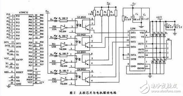
In the design, AT89C52 is the main control chip. In the cooperation of software, P0 and P1 are used as sensor signal input ports. Scanning multiple points (designed as 16 points, which can also be expanded according to specific conditions), monitoring information of infrared sensors, information is calculated. After processing, the P2 port outputs a pulse to the motor drive circuit composed of L298N to drive the motor to rotate a certain angle, thereby driving the camera on the pan/tilt to rotate at a certain angle (the horizontal direction is a multiple of 45°, the minimum is 45°, and the maximum is 315°; The vertical direction is a multiple of 15°, the minimum is 15°, and the maximum is 75°, which can be modified by software) to achieve automatic control. The motor uses a four-phase stepping motor, each motor is controlled by a four-position I/O port, so the lower four bits of the P2 port control the horizontal direction motor, and the upper four bits control the vertical direction motor. In the horizontal and vertical directions, the motor has the same driving principle except for the different rotation angles.

Figure 2 shows the main control chip and the horizontal drive circuit. In order to avoid the interference of the single-chip microcomputer when the motor is working, the inverter is added with an inverter and an optocoupler to isolate the drive, so that the MCU can work stably and reliably.
Human body infrared sensor acquisition circuit
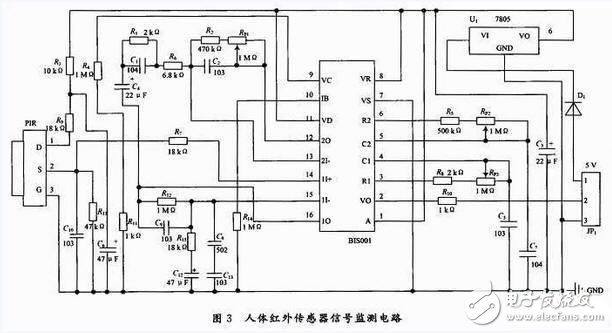
PIR is a sensor that detects changes in the infrared energy of human or animal radiation in a non-contact manner and converts it into a voltage signal output. BIS0001 is a high-performance signal processing integrated circuit consisting of an operational amplifier, a voltage comparator, a delay time, and a blocking time timer. It can form a passive human body infrared sensor acquisition circuit with PIR and a small number of external components.

Figure 3 shows the human body infrared sensor signal monitoring circuit. The PIR in the circuit uses LHl778 to monitor the human body's infrared signal. The acquired signal is amplified by BIS0001 and then output to the microcontroller for processing in the form of high and low level, thus realizing the signal to the fortified area. collection. In the designed monitoring circuit, the sensitivity of the PIR probe can be adjusted by adjusting the precision potentiometer Rp1 to control the sensing distance. The default is 5 m; the output delay time (Tx) of the Rp3 control signal is adjusted, Tx≈49 152&TImes; R8Rp3C5, The default is Tx≈1 s; the output blocking time (TI) of the Rp2 control signal is adjusted. The monitoring circuit outputs a low level at this time. TI≈24&TImes; R5Rp1C7, the default is 1.2 s, so it can be controlled by combining Tx and Ti. Monitor the detection period of the circuit. The PIR probe was treated in two ways to achieve control of its monitored area. When the self-made metal frame is applied, the detection of the fan-shaped area with a radius of 5 m and 45° can be realized. When a hollow metal sleeve with an inner diameter of 7 cm is applied, the detection range becomes a straight line with a length of about 5 m. After many verifications, the sensor has reached the design function.
Camera mounting platform
The stepping motor is an open-loop control element that converts the electric pulse signal into angular displacement or linear displacement. The speed and stop position of the motor depend on the frequency and pulse number of the pulse signal, the precision is high, and the step angle is smaller, the output torque is The larger the load, the stronger the load capacity. The design uses a four-phase stepper motor, which has three working modes: single four-shot, double four-shot, eight-shot, with a step angle of 1.8° for four beats and a step angle of eight for eight beats. Considering the requirement of high step precision and large output torque, the motor is operated in the eight-shot mode, and the motor is turned on in turn according to (A-AB-B-BC-C-CD-D-AD-A). The power is reversed in the opposite direction, and the motor speed can be controlled by controlling the energization time between each pulse. The camera mounting platform consists of a vertical placement and a horizontally placed stepper motor, ie a pan/tilt head, which can be rotated up and down and left and right to drive the camera for all-round monitoring.
Test Results
After the software debugging was successful, the physical production was carried out, and the functional requirements were verified by functional tests. In the test, the fan-shaped area with the pan-tilt as the center in eight directions and 45° in each direction was monitored. Each area was set with two points and a total of 16 points of information to verify the design function. The four images shown in Figure 5 are screen shots of the video screen taken by the camera (computer camera simulation) when the MCU automatically controls the pan/tilt when someone enters. In the test, A1A2, B1B2, C1C2, D1D2, E1E2, F1F2, G1G2, H1H2 represent eight directions respectively, subscript 1 indicates the nearest detection point (such as A1 ~ H1) from the center, and subscript 2 indicates that it is slightly from the center. A far circle of detection points (such as A2 ~ H2), 16 points constitute a polar coordinate system centered on the gimbal, test in these 16 positions, set the initial position of the camera as A1 area.
When no one enters the sensor monitoring area, the camera on the pan/tilt stays at the initial position. When the person enters the sensor detection area from any of the eight directions centered on the gimbal, the motor can drive the camera to achieve horizontal and vertical alignment. Rotating up and down, always makes people in the center of the camera's viewing angle range, enabling all-round intelligent tracking and surveillance. After many tests and data analysis, the intelligent control PTZ can enter the normal working state according to the design requirements after power-on and the accuracy is high, which confirms the feasibility and reliability of the solution.
The design mainly uses the single-chip microcomputer as the control core, combined with the multi-point signal acquisition circuit composed of the human body infrared sensor and the L298N drive circuit to control the pan/tilt, and carries out all-round automatic tracking and imaging for the intruders moving into the fortification area. The pan/tilt has high rotation angle precision, strong load capacity, stable operation, and no work when no one is working, which is energy-saving. Compared with the high-speed spherical and remote control pan/tilt currently on the market, the pan/tilt has the advantages of intelligent convenience, energy saving, low production cost and easy maintenance. Therefore, the cloud platform designed by this method has strong practical value and practical significance in the fields of intelligent control and monitoring after a certain processing.
Red IDC Connector:IDC connector Automotive Connector is a kind of component that electronic engineering and technical personnel often contact. Its function is very simple: in the circuit is blocked or isolated between the circuit, set up a bridge of communication, so that the current flow, so that the circuit to achieve the intended function. The form and structure of automobile connector are changeable. It is mainly composed of four basic structural components: contact, shell (depending on the variety) and insulator.
Red IDC Connector
ShenZhen Antenk Electronics Co,Ltd , https://www.pcbsocket.com