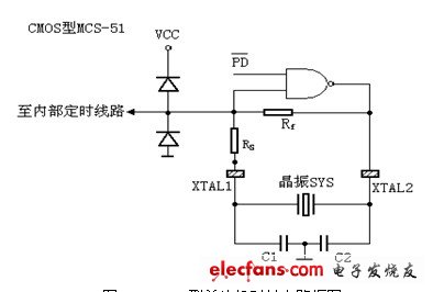
The MCS-51 has an inverting amplifier inside. XTAL1 and XTAL2 are the input and output terminals of the inverting amplifier respectively. The external timing feedback component is used to form the oscillator, and the clock is sent to the internal components of the microcontroller. The AT89C51 is a CMOS 8-bit microprocessor, and its clock circuit is different in structure from the NMOS type microcontroller.
Inside the CMOS type MCU (such as AT89C51), there is a controllable negative feedback inverting amplifier, an external crystal oscillator (or ceramic resonator) and a capacitor to form an oscillator. The following figure shows the CMOS type MCU clock circuit block diagram. The oscillator is controlled by the /PD terminal. The software sets "1" PD (that is, the special function register PCON.1) to make /PD=0, the oscillator stops working, and the whole microcontroller stops working to achieve power saving. Clear "0" PD, make the oscillator work to generate the clock, and the microcontroller will run normally. In the figure, SYS is a crystal or ceramic resonator, and the clock frequency generated by the oscillator is mainly determined by the SYS parameter (the frequency indicated on the crystal). Capacitors C1 and C2 function in two ways: one is to start the oscillator, and the other is to fine-tune the frequency f of the oscillator (C1, C2 is large, f is small), which is typically 30pF.

Figure CMOS type microcontroller clock circuit diagram
Dp Switcher,Hdmi Dp Switch,Dp Hdmi Switch,Switch Hdmi Dp
Dongguan Tuojun Electronic Technology Co., Ltd , https://www.fibercablessupplier.com