Probe - the key to measuring quality!
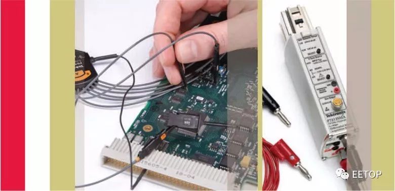
The probe is crucial for oscilloscope measurements. In order to understand its significance, the probe is not connected to the oscilloscope and the measurement is attempted. As a result, measurement cannot be performed. There must be some type of electrical connection between the signal being measured and the input channel of the oscilloscope, that is, some kind of probe.
In addition to probes that are critical to oscilloscope measurements, probes are also critical to measurement quality. Connecting the probe to the circuit can affect the operation of the circuit. The oscilloscope can only display and measure the signal that the probe transmits to the oscilloscope input.
Therefore, the influence of the probe on the detected circuit must be minimized and sufficient signal fidelity be maintained for the desired measurement. If the probe does not maintain signal fidelity, if it changes the signal or changes the way the circuit operates in any way, the oscilloscope will see the distortion of the actual signal, which may result in erroneous measurements or misleading measurements.
Probe Selection Guide
How does a signal source convert its properties to the corresponding probe selection index? As before, our goal is to select the probe that best probes the signal to the oscilloscope. However, it does not stop there. The oscilloscope presents certain requirements that must be considered during the selection of the probe.
This chapter examines various types of selection requirements. We first describe the requirements of the signal source.
Select the appropriate probe
Due to the wide range of oscilloscope measurement applications and requirements, there are many oscilloscope probes available on the market, so the probe selection process is easily confused.
To reduce a lot of confusion and narrow the selection process, it is important to always observe the oscilloscope manufacturer's probe recommendations. Because different oscilloscopes have different bandwidth, rise time, sensitivity and input impedance. Taking full advantage of the oscilloscope's measurement capabilities requires the probe to match the oscilloscope's design.
In addition, the probe selection process should consider the measurement requirements. Which items do you want to measure? Is it voltage? Current? Or light signal? By selecting the appropriate signal type of probe, direct measurements can be obtained more quickly.
Also, consider the measured signal amplitude. Are they within the oscilloscope's dynamic range? If not, it is necessary to select a probe that can adjust the dynamic range. In general, this is achieved by using a 10X or higher probe for attenuation.
Make sure the bandwidth or rise time on the probe exceeds the signal frequency or rise time that you plan to measure. Keep in mind that non-sinusoidal signals have important frequency components or harmonics that can largely exceed the fundamental frequency of the signal. For example, to measure the 5th harmonic that includes a 100 MHz square wave, you need a 500 MHz bandwidth measurement system on the probe. Similarly, the rise time of the oscilloscope system should be 3-5 times faster than the signal rise time of the planned measurement.
In addition, always consider the signal load that the probe may cause. Use high-resistance, low-capacitance probes whenever possible. For most applications, a 10M probe with a 20pF or lower capacitor should provide adequate signal source loading. However, for some high-speed digital circuits, you may need to switch to active probes to provide lower capacitance.
Finally, remember that you must be able to connect the probe to the circuit before taking measurements. This may require selective consideration of probe head specifications and probe adapters to easily and conveniently connect circuits.

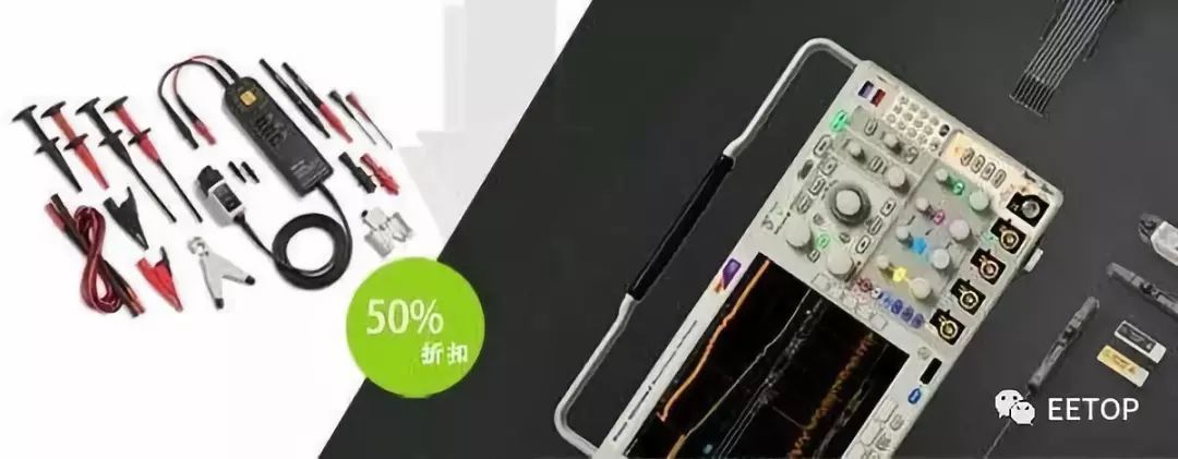
Accurate testing must also be equipped with the original probe! You don't have to worry about expensive probes. Tektronix has launched a 50% discount on probes purchased with the MDO4000C oscilloscope to solve your testing problems! Event Details
Understand the source
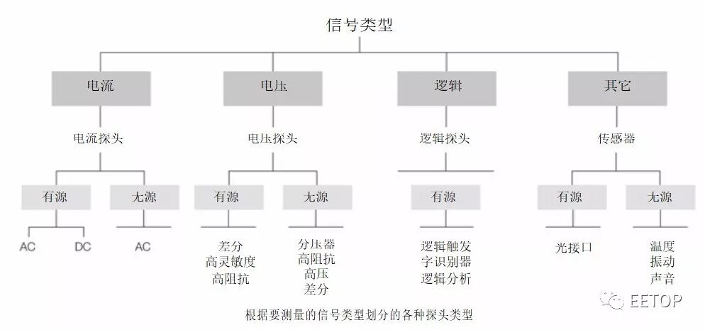
There are four basic signal source issues to consider when choosing a probe: signal type, signal frequency content, signal source impedance, and the physical properties of the test point.
Signal Type: The first step in probe selection is to evaluate the type of signal to probe. To do this, divide the signal into:
â– Voltage signal
â– Current signal
â– Logical signals
â– Other signals
Voltage signals are the most common type of signal encountered in electronic device measurements, and because of this, voltage-sensing probes are the most commonly used oscilloscope probe types. In addition, it should be noted that since the oscilloscope requires a voltage signal at the input, other types of oscilloscope probes are essentially converters that convert the sensed phenomenon into a corresponding voltage signal. A common example is a current probe that converts a current signal into a voltage signal for viewing signals on an oscilloscope.
The logic signal is actually a special type of voltage signal. Standard voltage probes can be used to view logic signals, but more often it is necessary to view specific logic events. A logic probe is set up to provide a trigger signal to the oscilloscope that allows the specified logic event to be viewed on the oscilloscope display when the specified logic combination trigger condition is met.
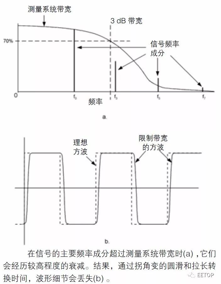
The main effect of limiting bandwidth is to reduce the signal amplitude. The closer the base frequency of the signal is to the probe's 3dB bandwidth, the lower the overall signal amplitude seen at the probe output. At the 3dB point, the amplitude drops by 30%. In addition, due to bandwidth roll-off, signal harmonics or other frequency components that extend above the probe bandwidth experience a higher degree of attenuation. Attenuation is higher at higher frequency components, as can be seen by changes in corners and slower transitions in the fast waveform (see the figure below).

It should also be noted that the probe capacitance also limits the rise time of the signal transitions. However, this is related to the source impedance and source loading.
Source impedance
Discussing the source impedance impedance can be refined into the following points:
1. The impedance of the probe is combined with the signal source impedance to generate a new signal load impedance, which will affect the signal amplitude and signal rise time to some extent.
2. When the probe impedance is significantly higher than the signal source impedance, the probe's effect on the signal amplitude is negligible.
3. The probe capacitance, also called input capacitance, affects the rise time of the signal. This is due to the time required to increase the input capacitance of the probe from 10% to 90%. Its formula is as follows:
Tr = 2.2 x Rsource x Cprobe
From the above points, it is clear that the best choice for high-impedance, low-capacitance probes to minimize the signal source of the probe load. In addition, the influence of the probe load can be further reduced by selecting a low-impedance signal test point where possible.
Physical connection considerations
The location and shape of the signal test points are also the main considerations for probe selection. Is it enough to just touch the probe to the test point and observe the signal on the oscilloscope? Is it still necessary to connect the probe to the test point to monitor the signal and perform various circuit adjustments at the same time? In the former case, needle probes are suitable; in the latter case, certain types of retractable hook probes are required.
The specifications of the test points also influence the probe selection. Standard size probes and accessories are particularly suitable for probing connector pins, resistor leads, and backplanes. However, in order to detect surface-encapsulated circuits, we recommend using small probes with specially designed accessories for surface mount applications. The goal is to choose the probe size, shape, and accessories that best suit the particular application, so that the probe can be quickly, easily, and firmly attached to the test point for reliable measurements.
Oscilloscope problems: The effects of oscilloscope problems on probe selection are just as important as signal source problems. If the probe and the oscilloscope do not match, the signal fidelity on the oscilloscope end of the probe will be impaired.
Bandwidth and Rise Time: It must be realized that the oscilloscope and its probe work together as a measurement system. Therefore, the oscilloscope bandwidth and rise time specifications used should be greater than or equal to the used probe metrics, making it sufficient to measure the signal.
These probe amplifier systems are highly specialized and are designed to match the specific oscilloscope model. As a result, when selecting an oscilloscope, it is important to check the manufacturer's recommended accessories for the differential probe system to meet the requirements for small signal applications.
Note: Differential probe systems often contain sensitive devices. Overvoltage can damage these devices, including electrostatic discharge. To avoid damaging the probe system, always follow the manufacturer's recommendations and observe all precautions.
Reading function. Most modern oscilloscopes provide vertical sensitivity and horizontal sensitivity settings (volts/div and seconds/div) readings on the screen. These oscilloscopes often also provide probe sensing and reading processing so that the readings correctly track the type of probe being used. For example, if you use a 10X probe, the oscilloscope should generally reflect the sensitivity by adjusting the vertical reading with a 10X factor. If a current probe is used, the vertical reading will change from volts/div to amperes/div to reflect the correct unit of measurement.
To use these reading functions, use a probe that is compatible with the oscilloscope reading system. The manufacturer's recommendations for using the probe with a specific oscilloscope should also be followed. This is especially important for new oscilloscopes, which may have many advanced reading features that are not fully supported by general purpose or commercial probes.
Choose the right probe
From the source and oscilloscope problems discussed earlier, it is apparent that choosing a proper probe is a very cumbersome process if not helpful. In fact, because certain key selection criteria such as probe rise time and oscilloscope input capacitance have not always been specified, in some cases the selection process may become guesswork.
To avoid guesswork, it is best to include an adapter that allows wide choice of probes in the list of recommended accessories. In addition, when new measurement requirements are encountered, it is important to check with the oscilloscope manufacturer for new probes that may extend the capabilities of the oscilloscope.
Finally, keep in mind that for any given application, there is actually no "proper" probe selection, but only the "suitable" oscilloscope/probe combination options, which first depend on the defined signal measurement requirements, including:
â– Signal type (voltage, current, optical interface, etc.)
â– Signal frequency component (bandwidth problem) Signal rise time
â– Source Impedance (Resistance and Capacitance)
â– Signal amplitude (maximum, minimum) Test point shape (leaded device, surface package, etc.)
By considering the above problems and filling out specific application information, you can find an oscilloscope and various compatible probes that can meet all application requirements.

Accurate testing must also be equipped with the original probe! You don't have to worry about expensive probes. Tektronix has launched a 50% discount on probes purchased with the MDO4000C oscilloscope to solve your testing problems!
Fiber Optical Patch Panel,Fiber Optic Patch Panel,Fiber Optic Patch Panel Accessories,Fiber Optic Patch Cord Adapter
Huizhou Fibercan Industrial Co.Ltd , https://www.fibercan-network.com