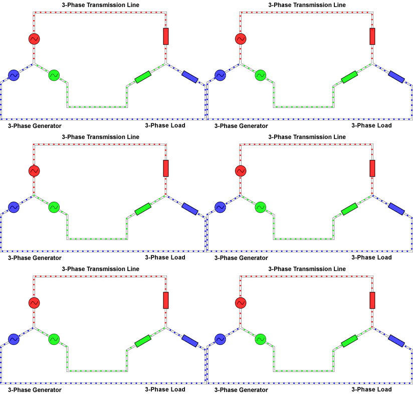
Three-phase alternating current is a frequent visitor in life. In a specific environment, due to the use load of high-power electrical equipment, three-phase electricity is required, which is a form of transmission of electric energy, which is simply referred to as three-phase electricity. The three-phase AC power supply is a power supply composed of three alternating current potentials of the same frequency, equal amplitude, and phase difference of 120°.
Three-phase power characteristics1, three-phase electricity is a fire line, touch that one is not, between the two is 380V, between each and the zero line is 220V, which is what we use every day.
2, three-phase power can be connected to the motor, three into the motor at the same time, there are star connection and delta connection.
3. The voltage of the two is 380V instead of 220V.
4, you can use one of them and the zero line to form 220V.
5. The neutral line is generally used to turn on the unbalanced current when the three-phase load is unbalanced.
The neutral line is the line from the neutral point of the transformer, and the phase line forms a loop to supply power to the electrical equipment. Under normal circumstances, the neutral line is repeatedly grounded at the neutral point of the transformer and the ground line, and the double protection voltage is two points. The potential difference is the equipotential body that is the reference point of the circuit potential.
Mathematical equation of three-phase AC voltageV1 = Asin(2Ï€ft)=Asin(wt)
V2 = Asin(2Ï€ft - 2Ï€/3)=Asin(wt-2Ï€/3)
V3 = Asin(2Ï€ft + 2Ï€/3)=Asin(wt+2Ï€/3)
Where A is the peak value of the voltage and f is the frequency of the AC voltage.
The difference between three-phase electricity and two-phase electricity
The difference between three-phase power and two-phase power is that the three-phase power has two more fire lines than the two-phase power, and the voltage levels are different, the three-phase power is 380V, the two-phase power is 220V, and the three-phase power is also used in enterprises and factories. For example, the power supply of large equipment such as motors and pumps, and the two phases are mostly used for household, school, hotel and other household appliances, single-phase electricity, two-phase electricity, three-phase electricity is low-voltage three-phase four-wire (380V/220V) Predicate in the power supply system. The single phase represents the neutral line (neutral line) and any phase line (A, B, C), and the voltage is 220V. The two phases represent any two-phase line (AC, AB, BC) and the voltage is 380V. The three phases represent a three-phase (A, B, C) line consisting of 120 degrees difference, 3Φ380V. For electrical loads, there are two connections for three phases (star and triangle).
The difference between three-phase electricity and single-phase electricityThe difference between three-phase power and single-phase power: single phase is 220V, which is the voltage between the phase line and the zero line. The three-phase is the phase-to-phase voltage of 380V between ABC, and the electric appliance is a three-phase electric 380V motor or equipment. The power generated by the generator is three-phase. Each phase and neutral point of the three-phase power supply can form a single-phase loop to provide power for the user. Note that in the AC circuit, it cannot be called positive or negative, it should be called phase line (called live line in civil power) and neutral line (called neutral line in civil power).
Three-phase electrical principleAn example is used to explain the three-phase electrical principle. Although it is shallow and simple, it can be quickly understood.
Three people stand on the three vertices of the regular triangle. The A phase person pushes it first, then the B phase person, then the C phase, and turns the wheel, and the wheel keeps turning. If someone uses a big force, the three phases will be unbalanced, the support point will sway, and the support point will have a reaction force [neutral point (N line) has current through], if the wheel has no resistance, it will The occurrence of a flying car phenomenon is equivalent to a short circuit phenomenon, and the three-phase power is roughly like this.
Three-circuit circuit compositionThe three items are generally AC, there is a phase deviation, and the current will automatically go from high voltage to low voltage. For example, the electric welder is connected to one of the three items. Here, it is called u, v phase, which is 380v. At some point, when the u phase is high voltage, the v phase is low voltage, so there is a phase between the high and low voltages. Poor, there will be current flowing through, forming a loop. Of course, there are times when v is high!


Each waveform of the three-phase power is a single sine, but the phase angles are 120 degrees apart. The tri-electricity is the minimum number of phases that can produce a fixed starting torque in the rotor of the motor.
Three-phase electrical connectionThe three-phase power consists of three AC voltages of the same frequency and similar amplitude. Each ac voltage "phase" is 120° apart from the other ac voltage (Figure 1). This can be represented graphically, using waveforms and vector graphics (Figure 2).

Figure 1. Three-phase voltage waveform

Figure 2. Three-phase voltage vector
There are two reasons for using a three-phase system:
1. A three-vector voltage can be used to generate a rotating magnetic field in the motor. This makes it possible to start the motor without the need for additional windings.
2. A three-phase system can be connected to the load and the required number of copper connections (transmission loss) is half that of the other methods.
Let's look at three single-phase systems, each providing 100W of power for one load (Figure 3). The total load is 3 x 100W = 300W. To provide power, 1 amp of current flows through 6 lines, so there are 6 units of losses. It is also possible to connect three power supplies to a common backhaul, as shown in Figure 4. When the load current in each phase is the same, the load is considered to be balanced. In the case of load balancing, and the three current phases are shifted by 120° from each other, the sum of the currents at any point in time is zero, and there is no current in the return line.

Figure 3. Three single-phase power supplies - 6 unit losses

Figure 4. Three-phase power supply, balanced load - 3 unit losses
In a three-phase 120° system, three wires are required to transmit power, while in other modes six wires are required. The required number of copper cables is reduced by half and the wire transmission losses are also halved.
Y-joint or star connection
A three-phase system with a common connection is generally shown in the schematic diagram of Figure 5 and is referred to as a "Y or star" connection.
A common point is called a neutral point. For safety reasons, this point is usually grounded on the power supply. In practice, the load is not perfectly balanced, and the current is transmitted using the fourth "neutral" line. Neutral conductors may be much smaller than the three main conductors if allowed by local regulations and standards.

Figure 5. Y-connection or star connection - three-phase four-wire
Delta connection
The three single-phase power sources discussed above can also be connected in series. At any point in time, the sum of the three 120° phase shift voltages is zero. If the sum is zero, then both endpoints are at the same potential and can be joined together. This connection is shown in the schematic diagram of Figure 7, using the Greek letter Δ, called the delta connection.

Figure 6. The sum of the instantaneous voltages at any time is zero

Figure 7. Delta connection - three-phase three-wire
Comparison of Y-shaped connection and delta connection
The Y-connection is used to power everyday single-phase devices used in homes and offices. A single phase load is connected to one leg of the Y-shape between the line and the neutral. The total load for each phase is shared as much as possible to provide a balanced load for the main three-phase power supply.
The Y-junction also provides single or three phase power for higher power loads at higher voltages. The single phase voltage is a phase to neutral voltage. A higher phase-to-phase voltage is also provided, as shown by the black vector in Figure 8.

Figure 8. V phase-phase = √3 x V phase-neutral
The most common case of delta connection is to power a three-phase industrial load with higher power. However, by connecting or "striping" along the transformer coil, different voltage combinations can be obtained from the three-phase delta power supply. For example, in the United States, a 240V delta system can have split or center tap coils that provide two 120V supplies (Figure 9). For safety reasons, the center tapping point can be grounded on the transformer. Between the center tap and the third "high" of the delta connection, a voltage of 208V is also provided.

Figure 9. Delta connection with "phase separation" or "center tap" coil
Power measurement
In an AC system, power is measured using a power meter. The modern digital sampling power meter multiplies the instantaneous samples of multiple voltages and currents to calculate the instantaneous power, and then takes the average of the instantaneous power in one cycle to indicate the active power. The power meter accurately measures active power, apparent power, reactive load, power factor, harmonics, etc. over a wide range of waveforms, frequencies, and power factors. In order for the power analyzer to provide good results, the wiring configuration must be properly identified and the power analyzer properly connected.
Single phase power meter connection
Only one power meter is required, as shown in Figure 10. The connection between the system and the power meter voltage terminal and current terminal is straightforward. The voltage terminals of the power meter are connected in parallel through the load, and the current is input through a current terminal connected in series with the load.

Figure 10. Single-phase two-wire and DC measurements
Single phase three phase connection
In this system, as shown in Figure 11, a voltage is generated from a centrally tapped transformer coil, all voltages being in phase. This is common in residential applications in North America, where a 240 V power supply and two 120V power supplies are provided, with different loads on each leg line. To measure total power and other quantities, connect two power meters as shown in Figure 11.

Figure 11. Single-phase three-wire
Browndale's theorem: the number of power meters required
In a single phase system, there are only two wires. Power is measured using a power meter. In a three-wire system, two power meters are required, as shown in Figure 12.
In general, the number of required power meters = number of lines - 1

Figure 12. Three-wire Y-shaped system
Verify the three-phase Y-shaped system
The instantaneous power measured by the power meter is the product of the instantaneous voltage and current samples.
Power meter 1 reading = i1 (v1 - v3)
Power meter 2 reading = i2 (v2 - v3)
The sum of readings W1 + W2 = i1v1 - i1v3 + i2v2 - i2v3
= i1v1 + i2v2 - (i1 + i2) v3
(According to Kirchhoff's law, i1 + i2 + i3 = 0, so i1 + i2 = -i3)
2 readings W1 + W2 = i1v1 + i2v2 + i3v3 = total instantaneous power.
Three-phase three-wire connection - two power meter methods
When there are three wires, two power meters are required to measure the total power. Connect the two phases to the voltage terminals of the power meter according to the method shown in the figure.

Figure 13. Three-phase three-wire, two power meter methods
Three-phase three-wire connection - three power meter methods
As mentioned earlier, although only two power meters are required to measure the total power in a three-wire system, it is sometimes convenient to use three power meters. In the connection shown in the figure, a false neutral is created by connecting the low voltage terminals of all three power meters together.

Figure 14. Three-phase three-wire (three power meter methods, setting the analyzer to three-phase four-wire mode)
The advantage of the three-wire three-power meter connection is that it indicates the power of each phase (which is not possible in the connection of the two power meters) and the phase-to-neutral voltage.
Three-phase four-wire connection
Measuring the total power in a four-wire system requires three power meters. The measured voltage is the true phase voltage. By using vector math operations, the phase-to-phase voltage can be accurately calculated from the amplitude and phase of the phase voltage. Modern power analyzers also use Kirchol's law to calculate the current flowing through the neutral line.

Figure 15. Three-phase four-wire (three power meter methods)
A new rule from the Drug Enforcement Administration (DEA) threatens to upend the American hemp industry, and could even result in criminal prosecutions for manufacturers of CBD and delta-8 THC products.
The DEA says the [interim final rule," issued Aug. 20, is simply a matter of adjusting its own regulations to account for changes to the Controlled Substances Act that were mandated by the 2018 Farm Bill (or Agricultural Improvement Act) that legalized hemp and CBD production. The new rule [merely conforms DEA`s regulations to the statutory amendments to the CSA that have already taken effect," says the agency. The new rule doesn`t break any ground, according to the DEA.
But many experts on cannabis and hemp law say the DEA rule creates a potential pathway the law enforcement agency could use to prosecute hemp processors and producers of CBD (cannabidiol) and delta-8 THC (or Δ8THC) products. There are two issues: partially processed CBD, and [synthetically derived" delta-8 THC.
Cbd Pod System Oem,Cbd Vape Pod Oem,Best Cbd Pod System,Cbd Pod System
Shenzhen MASON VAP Technology Co., Ltd. , https://www.cbdvapefactory.com