introduction
With the rapid growth of the number of cars, the quantity and quality of automotive testing equipment are constantly improving. As an important part of vehicle detection, the impact of wheel alignment parameter detection on the safety performance of the vehicle is very important. If the wheel positioning parameters are not normal, it will lead to abnormal wear of the tire, running deviation, wheel swaying, heavy steering, and increased fuel consumption, which directly affect the driving safety of the car.
This article refers to the address: http://
The traditional four-wheel aligners are mainly laser, infrared, level, optical and cable. At present, the latest four-wheel positioning products in the automobile detection industry at home and abroad are image-based four-wheel aligners based on computer vision. This locator is based entirely on computer image processing technology, requiring only two high-performance CCD sensor cameras with four target discs mounted on the wheels (as shown in Figure 1), eliminating the need for traditional electronic sensors, eliminating the possibility of circuit failure. Compared with the traditional four-wheel aligner, the number of sensors is greatly reduced, and it is not necessary to perform repeated calibration. It can be reused in one calibration, and the operation is simple, the detection speed is fast, and the precision is high.
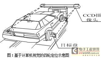
The product is technologically advanced. At present, it mainly relies on imports and is expensive. The foreign manufacturers are strictly confidential on its principle, and no detailed reports have been reported in China. Therefore, the principle is divided into foreign perspective-based methods and the space vector based method is analyzed and discussed in detail. The mathematical model based on space vector method is given, and its effectiveness is verified by real vehicle experiments.
1. Based on perspective
This principle is used by foreign V3D locators (such as the US JohnBean locator). When the method detects, the camera captures the wheel motion (target disk), compares it with the known data after image processing, and accurately calculates the target from the position and size of the target disk reflection spot according to the perspective and analytical geometry principle. The geometric parameters such as camera distance and rotation angle are calculated, and then the data of the wheel is used to calculate the positioning data of each wheel.
1.1 Fundamentals of perspective
This method needs to be applied to the perspective principle and perspective shortening principle in perspective [3]. Perspective is the observation of objects through imaginary transparent planes, and the study of the principle and variation of object graphics in a certain visual space.
Taking a circle as an example, as shown in Fig. 2(a), according to the perspective principle, when the circle is approached from a distance, the effect is that the visual size of the circle becomes larger and larger, that is, the image formed by the same object has Nearly large and small features. Apply this principle to measure the distance to the object;
As shown in Fig. 2(b), according to the principle of perspective shortening, when the circle rotates in the horizontal axis direction, its vertical dimension will become shorter and shorter, gradually becoming a line segment (the length is the diameter of the circle), when continuing When rotating, the line segment gradually expands into an ellipse and eventually changes back to a circle. During the rotation, the length (diameter) of the axis of the circle in the visual effect is constant. Therefore, the angle by which the circle is rotated in the horizontal axis direction can be calculated from the change in the height of the circle. Similarly, the angle at which the circle is rotated along the longitudinal axis can also be calculated. From the combination of the horizontal and vertical rotation effects of the circle, the angle of the circle rotated in any direction in space and the spatial position of its axis of rotation can be calculated.
1.2 Target distance and corner angle
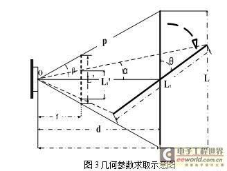
Due to the need to obtain the positioning parameters, the geometric parameters such as the distance and the angle of the camera to the observed target must be determined first, which can be obtained according to the trigonometric function and the basic geometric theory. 
As shown in Fig. 3, L is the target initial position, which is imaged L'; L1 is the position after L rotation θ, which images L1'. And the focal length f and the target actual size L (L1 = L) are known, and the imaging size L' of the target at the focal length can be calculated by the lens imaging formula. Get the formula (1).

When f, L, L' and p are known, the formula (2) can be obtained.

Similarly, the sum α after the rotation angle θ can be obtained, and θ can be obtained from α, L1, and d.
From the above process, the distance, the imaging size, and the spatial rotation angle are obtained.
1.3 Positioning parameters are obtained
This method generally selects a circle as a regular graph on the target disc. This is because the circle has unique geometric characteristics and is the most ideal graph for calculating related parameters. It is an axisymmetric figure and a centrally symmetrical figure; the positioning is based on three mutually perpendicular planes defined by the wheel axle: the body plane, the axle plane, and the wheel plane. The axle plane is the reference plane for the kingpin to lean backward; the wheel plane is the reference plane of the toe angle, the camber angle and the caster angle.
When the actual size of the target is known, and the distance from the observation point to the target at the camera, the imaging size and the rotation angle are obtained, the positioning parameter data can be calculated.
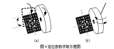
The target disk is mounted on the wheel at a certain angle by a clamp. When the vehicle moves back and forth, the wheel and the target disk rotate together back and forth, and the front toe angle can be detected by detecting the rotation of the circle on the target disk along its longitudinal axis; At the same time, the symmetry line of the target disk in this process will form a set of vector curved surfaces, and the angle between the two symmetry lines of the target disk before and after the rotation is called the vector angle. From the vector angle, the camber angle of the wheel can be calculated [4] (as shown in Figure 4(a)).
When the vehicle is stationary, (as shown in Fig. 4(b)), the wheel and the target disk are rotated to the left or right, and the rotation of the disk on the longitudinal axis of the disk surface is detected to detect the kingpin inclination angle; The rotation of the circle along its horizontal axis can detect the caster angle of the kingpin.
This method is relatively simple in principle. It is a foreign patented technology. Although there are certain requirements on the shape of the target disk, etc., the calculation process is simple and ingenious, easy to achieve fast positioning, and there is no strict requirement for the positioning platform.
2, based on the way of space vector
The method is to take a front and rear shooting of a target disk (with regular markings) mounted on a wheel, and then perform image processing and analysis to extract feature points on the target disk, and then change the spatial coordinates according to the position of the feature points. The space rotation vector of the wheel is calculated, and the positioning parameter is obtained from the angle relationship between the vector and the coordinate axes of the space coordinate system.
2.1 Reference coordinate system
In computer vision, three coordinate systems of world coordinate system, camera coordinate system and image coordinate system are needed.
The world coordinate system (Xw, Yw, Zw) is a reference coordinate system selected in the environment to describe the camera position, and can be freely selected according to the principle of description and calculation convenience. For some camera models, choosing the appropriate world coordinate system greatly simplifies the mathematical expression of the visual model.
The camera coordinate system (Xc, Yc, Zc) takes the camera lens optical center Oc as the coordinate origin, the Xc and Yc axes are parallel to the imaging plane, and the Zc axis is perpendicular to the imaging plane. The coordinates of the intersection point on the image coordinate system are (u0, v0). ), the camera's main point.
The image coordinate system is a Cartesian coordinate system defined on a two-dimensional image, which is divided into two units of pixels and a physical length (such as millimeters), which are represented by (u, v) and (x, y), respectively. As shown in Figure 5. The most common is the coordinate system in pixels, usually its coordinate origin is generally defined in the upper left corner of the image.
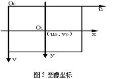
Let the physical size of each pixel of the camera CCD in the X-axis and Y-axis directions be dx, dy (this parameter is provided by the camera manufacturer, which is a known parameter, and its ratio dy/dx is called Aspect Ratio, ie aspect ratio), Fig. 5 shows that the relationship between the pixel value (u, v) and the coordinates (x, y) on the image is expressed by the homogeneous coordinate and the matrix as the equation (3).

2.2 Camera model
The pinhole model is derived from the principle of small hole imaging. It is a linear camera model obtained by adding rigid body transformation (rotation and translation of rigid body) based on simple central projection (also called perspective projection). It does not consider the distortion of various lenses, but it can simulate the actual camera very well, which is the basis of other models and calibration methods.
Let P be a point in space, the coordinates in the camera coordinate system are (Xc, Yc, Zc); q is the corresponding point on the P imaging plane, the coordinate of q is (x, y), and f is the focal length of the camera. According to the proportional relationship of the perspective projection, the equation (4) is used.

2.3 Find the coordinate transformation relationship
As part of the process of solving the parameters, the target disk is pre-shot, and the world coordinates of the target disk feature points are obtained by extracting the pixel coordinates of the feature points on the image. Here, the conversion relationship between the world coordinates and the ideal image pixel coordinates will be established on the basis of the pinhole model.
The geometric features and rules of the target disk surface are known. The world coordinate system is built on the disk surface, and the feature point world coordinates can be known, and Zw=0. Let the coordinates of one point P(Xw, Yw, Zw) in the camera coordinate system be (Xc, Yc, Zc), and image the image on the CCD image plane after shooting, and set the coordinates of the imaging point to (x, y). The image pixel coordinates correspond to (u, v).
The first is the transformation of the spatial coordinate system. According to computer vision theory, the rigid body motion can be decomposed into the synthesis of rotation and translation. The world coordinate system can be converted to a camera coordinate system and converted to homogeneous coordinates, as shown in equation (5).
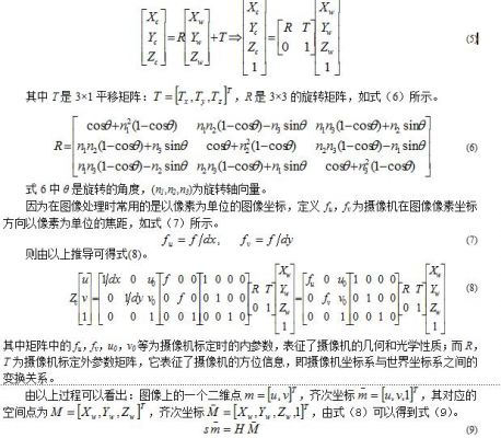
s is the scale factor and H is the homography matrix. Thereby, the correspondence between the image coordinates and the world coordinates can be established. Then, the known target disk feature point world coordinates and the extracted image pixel coordinates are substituted into equation (9), and their conversion relationships are obtained for subsequent calculation.
2.4 Positioning parameters to obtain
The motion of the wheel can also be seen as rigid body motion. At some point on the wheel (since the target disk is the same as the wheel motion, we study the point on the target disk fixed on the wheel), the motion is broken into a rotation around the axis of rotation. Pan.
Let the pair of corresponding points before and after the movement of the wheel (target disk) be P and P', and their world coordinate system coordinates are (Xw, Yw, Zw)T and (Xw', Yw', Zw')T, then change The formula is equation (10).

Where R, T is exactly the same as the expression in equation (5), but its meaning has changed. It is used to describe the transformation process at different spatial positions. θ in R is the angle of rotation around the axis of rotation on the wheel. N1, n2, n3) is the space vector of the wheel rotation axis; and R, T in equation (5) is used to describe the transformation relationship between the camera coordinate system and the world coordinate system.
According to the coordinate transformation relationship obtained in 2.3, the world coordinates of the space target disk before and after the motion are obtained by using the image coordinates, and then brought into equation (10) to obtain the rotation axis vector of the wheel motion (n1, n2, n3). . The angle α, β, γ between this vector and each coordinate axis Xw, Yw, Zw in the world coordinate system. Further, the positioning parameters can be obtained by using the included angle.
For convenience of explanation, as shown in Figure 6, let Zw be the direction of the car, Xw points to the left side of the car, Yw is perpendicular to the body plane, N wheel rotates the axis vector, N' is the translation of N, then β-900 is outside the wheel Inclination angle, arctan|cos γ / cos α | × 1800 / π is the toe angle.
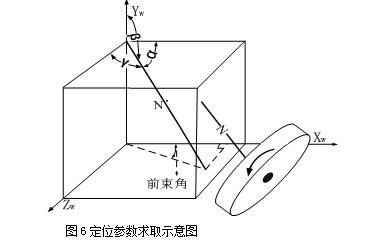
In the same way, the image of the car is rotated to the left or right by an angle, and the space vector of the kingpin is taken out, and the caster angle and the caster angle are obtained.
In this way, the rotation axis and the kingpin of the wheel are used in principle. Starting from the vector, the derivation process is more complicated, but the calculation result is relatively straightforward, and the requirements on the shape and positioning platform on the target disk are relatively low, and it is easy to achieve stable accuracy. Positioning.
3. Experimental results and analysis
The field experiment was carried out, and the wheel positioning parameters were detected by the current state-of-the-art chariot (JohnBean) image wheel aligner and the spatial vector-based measurement method proposed in this paper. The experimental vehicle is the Volkswagen Golf 2004 sedan. The self-made target board is used to verify the method. The regular pattern is set to the chessboard pattern, and the target disc is fixed on the front and rear wheels. A partial experimental image is shown in FIG. Taking the detection of the left wheel of the automobile as an example, taking the average of multiple measurement results as the final result, the experimental results are shown in Table 1. It can be seen from the results in Table 1 that the measurement results of this method are basically consistent with the measurement results of the wheel locator in the error tolerance range, which proves the correctness and effectiveness of the proposed model.
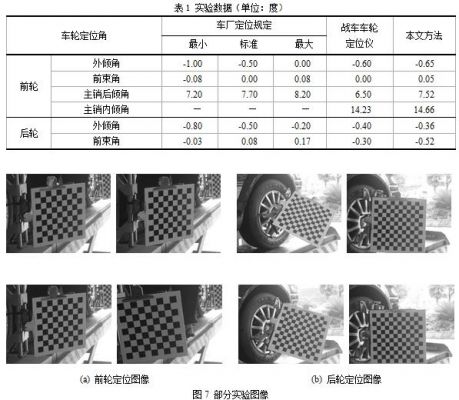
The main reason for the error is the accuracy of the self-made target board and the influence of image noise. The error is also affected by factors such as camera resolution, camera calibration, and corner coordinate extraction accuracy. Therefore, to improve measurement accuracy, the target board must be made as precise as possible, the resolution of the camera is as high as possible, and the camera calibration accuracy is improved.
4 Conclusion
The four-wheel alignment method based on computer vision makes full use of the visual theory, and skillfully uses the spatial geometry knowledge to realize accurate, fast and convenient detection of wheel positioning parameters. In this paper, the principle based on the perspective method and the principle based on the space vector method are discussed and analyzed. The mathematical model based on the space vector method is presented in this paper. The experimental results prove its correctness and effectiveness. Provided new ideas and new technologies for the domestic automotive electronics inspection industry.
High Voltage Lan Transformer,High Voltage Pwoer Pulse Transformer,Cmc Coilfor Automotive Product,High Voltage Pulse Transformer
IHUA INDUSTRIES CO.,LTD. , https://www.ihua-inductor.com