SVPWM is a relatively novel control method developed in recent years. It is a pulse width modulated wave generated by a specific switching mode composed of six power switching elements of a three-phase power inverter, which can make the output current waveform as close as possible to the ideal one. Sinusoidal waveform. The space voltage vector PWM is different from the traditional sinusoidal PWM. It starts from the overall effect of the three-phase output voltage and focuses on how to make the motor obtain the ideal circular flux linkage. Compared with SPWM, the SVPWM technology has a small harmonic component of the winding current waveform, which reduces the torque ripple of the motor, and the rotating magnetic field is closer to a circular shape. Moreover, the utilization of the DC bus voltage is greatly improved, and it is easier to digitize.
2.SVPWM basic principleThe theoretical basis of SVPWM is the principle of average equivalent, that is, by combining the basic voltage vectors in one switching cycle, the average value is equal to the given voltage vector.
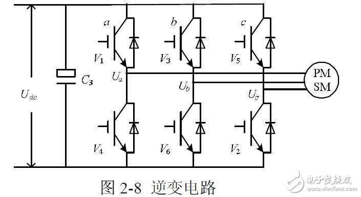
In the inverter circuit of the above figure, the voltage on the DC bus is Udc, and the three-phase voltages output by the inverter are UA, UB, and UC, which are respectively applied to a plane coordinate system that is spatially different from each other by 120 degrees. The three voltage space vectors are defined as UA(t), UB(t), UC(t), and their directions are always on their respective axes, and the magnitude changes according to the sine law with time, and the time phase is 120 degrees out of each other. Assuming Um is the effective value of the phase voltage and f is the power supply frequency, then there are:

It can be seen that U(t) is a rotating space vector whose amplitude is constant and is the phase voltage peak, and the space vector is rotated at a constant speed in the counterclockwise direction with the angular frequency ω= 2πf. The purpose of the SVPWM algorithm is to represent the U(t) vector that rotates in space using the switching state of the three-phase bridge.
Since the three-phase bridge arm of the inverter has a total of six switching tubes, in order to study the space voltage vector of the inverter output when the upper and lower bridge arms of different phases are combined, the special switching function Sx (x=a, b, c) is:

There are eight possible combinations of (Sa, Sb, Sc), including 6 non-zero vectors U1(001), U2(010), U3(011), U4(100), U5(101), U6(110) And two zero vectors U0 (000), U7 (111), the following one of the switch combination as an example analysis, assuming Sx (x = a, b, c) = (100), the equivalent circuit as shown :
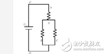
Therefore, the phase voltage can be expressed as: (the phase voltage is the voltage of each phase relative to the intermediate connection point of the motor)

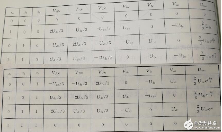
Similarly, the phase voltages of the three phases of other switching states are available. In addition, the line voltage is the voltage difference between the two phases, such as Uab=Ua-Ub. As mentioned before

When the switch Sa=1, UA(t)=Udc; when the switch Sb=1, UB(t)=Udc; when the switch Sc=1, UC(t)=Udc. So the above formula can be written as:

It can be seen that the modulus of Uout is unchanged, and only the phase is changed.
The switch state is listed with line voltage, phase voltage, and Uout:
Place the above eight voltage space vectors in the sector map according to the phase relationship of Uout:
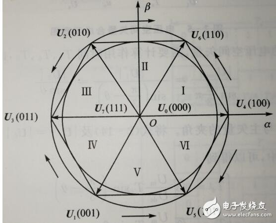
In the above figure, the six non-zero vectors have the same amplitude, and the adjacent vectors are separated by 60 degrees. The two zero vector magnitudes are zero and are centered.
When the voltage vector rotational angular velocity synthesized by the three-phase voltage reference is ω=2πf, the time required for one rotation is T=1/f; if the carrier frequency is fs, the frequency ratio is R=fs /f. In this way, the voltage rotation plane or the like is cut into R small increments, that is, the angle of each increment of the set voltage vector is: γ=2π/R.
Now suppose that we need to output a space vector Uref, assuming it is in the first sector, we first take the first sector separately and then use the two voltage space vectors adjacent to it to represent it:
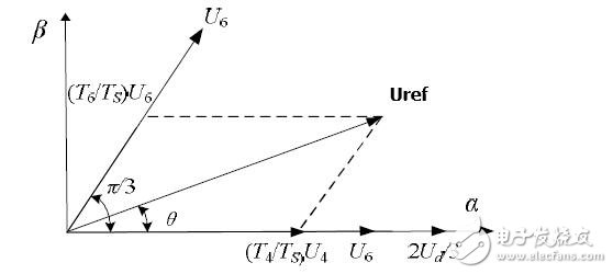
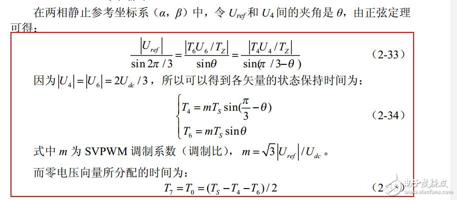
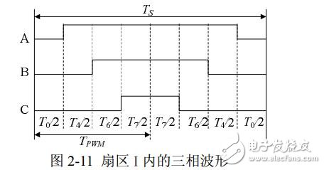
After getting the Uref synthesized by U4, U6, U7 and U0, the next step is how to generate the actual pulse width modulation waveform. In the SVPWM modulation scheme, the choice of zero vector is the most flexible. Appropriate selection of zero vector can minimize the number of switching, avoid switching at the moment when the load current is large, and minimize the switching loss. . Therefore, we aim to reduce the number of switching times, and the principle of assigning the basic vector action order is selected as follows: only change the switching state of one of the phases in each switching state transition. And the zero vector is evenly distributed over time to make the generated PWM symmetrical, thus effectively reducing the harmonic components of the PWM. It can be found that when U4(100) is switched to U0(000), it is only necessary to change the pair of upper and lower switches of phase A. If U4(100) is switched to U7(111), the two pairs of switches of B and C need to be changed. , doubled the switching loss. Therefore, to change the magnitude of the voltage vectors U4(100), U2(010), and U1(001), it is necessary to match the zero voltage vector U0(000), but to change U6(110), U3(011), U5(100), It is necessary to cooperate with the zero voltage vector U7 (111). In this way, symmetric output waveforms can be obtained by arranging different switching sequences in different intervals. The switching sequence of other sectors is shown in Table 2-2.

Therefore, you can use the combination of the order of U4, U6, U7, and U0 and the length of time to represent Uref.
Taking the first sector as an example, the three-phase wave modulation waveform generated in one carrier cycle time Ts is shown in Figure 2-11. The voltage vector appears in the order of U0, U4, U6, U7, U6. , U4, U0, the three-phase waveform of each voltage vector corresponds to the switch representation symbol in Table 2-2. After the next carrier period Ts, the angle of Uref is increased by γ, and the new T0, T4, T6 and T7 values ​​can be recalculated by using equation (2-33) to obtain a new synthetic three-phase waveform similar to that of Figure 2-11; Each carrier cycle TS will synthesize a new vector. As θ gradually increases, Uref will enter the I, II, III, IV, V, and VI regions in sequence. After the voltage vector is rotated for one cycle, R composite vectors are generated.
Therefore SVPWM will be calculated once per carrier cycle.
Through the above SVPWM rule derivation analysis, it is known that to realize real-time modulation of the SVPWM signal, it is first necessary to know the interval position of the reference voltage vector Uref, and then use the adjacent two voltage vectors of the sector and the appropriate zero vector to synthesize the reference voltage vector.
The control system needs to output a vector voltage signal Uref that rotates counterclockwise in space at a certain angular frequency ω. When rotated into a 60° sector of the vector diagram, the system calculates the basic voltage space vector required for the interval. The power switching element operates in the state corresponding to the vector. When the control vector is rotated 360° in space, the inverter can output a period of sine wave voltage.
1. Judgment of the sector N where the composite vector Uref is located
The first step in space vector modulation is to determine the sector in which the spatial voltage vector is determined by Uα and Uβ.
Assuming that the synthesized voltage vector falls in the first sector, the equivalent conditions are as follows: 0 "arctan(Uβ/ Uα) "60
The necessary and sufficient conditions for falling in the first sector are: Ua 》 0 , Uβ 》 0 and Uβ/Ua “√3.
Similarly, the equivalent condition that the synthesized voltage vector falls in other sectors can be obtained, and it is concluded that:
The necessary and sufficient conditions for Uref to fall in the second sector are: Ua "0" and Uβ/ Ua √ 3;
The necessary and sufficient conditions for Uref to fall in the third sector are: Ua "0, Uβ" 0 and -Uβ/Ua "√3;
The necessary and sufficient conditions for Uref to fall in the IV sector are: Ua "0, Uβ" 0 and Uβ/Ua "√3;
The necessary and sufficient condition for Uref to fall in the Vth sector is: Uβ “0 and -Uβ/Uaâ€âˆš3;
The necessary and sufficient conditions for Uref to fall in the VI sector are: Ua "0, Uβ" 0 and -Uβ/Ua "√3;
If the above conditions are further analyzed, it can be seen that the sector in which the reference voltage vector Uref is located is completely determined by Uβ, √3Ua-Uβ, -√3Ua-Uβ, so that:
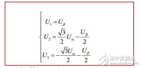
Redefinition, if U1 》 0, then A=1, otherwise A=0;
If U2 》 0, then B=1, otherwise B=0;
If U3 》 0, then C=1, otherwise C=0.
It can be seen that there are eight combinations between A, B, and C, but it is known from the formula for judging the sector that A, B, and C are not 1 or both, so the actual combination is six, A, B, The C combination takes different values ​​corresponding to different sectors, and is one-to-one correspondence, so the sector in which it is located can be judged by the combination of A, B, and C. To distinguish the six states, let N=4*C+2*B+A, then the sector in which the reference voltage vector Uref is located can be calculated from the following table.

With the above method, the sector can be determined by simple addition, subtraction and logic operations, which is meaningful for improving the response speed of the system and simulating the system.
2. Basic vector action time calculation and synthesis of three-phase PWM waveform
The spatial angle and trigonometric functions are used in the traditional SVPWM algorithm (2-34), making it difficult to directly calculate the fundamental voltage vector action time. In fact, the calculations can be greatly simplified by making full use of Uα and Uβ.
The analysis is performed when Uref is in the first sector, according to Figure 2-10:
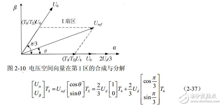

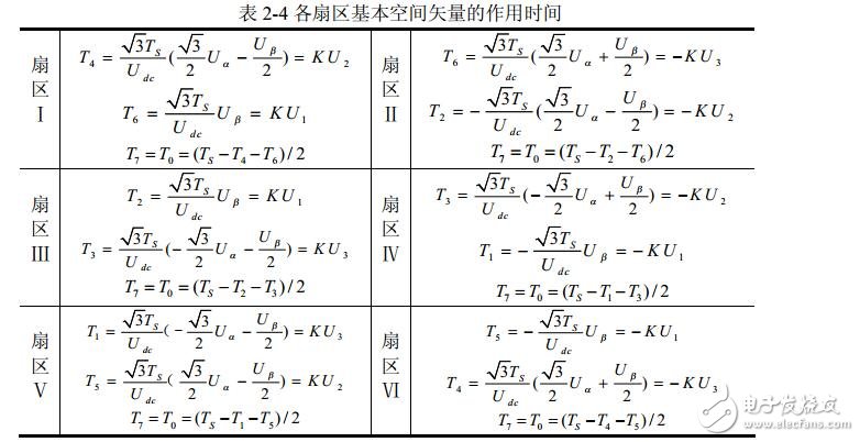
Similarly, the action time of each vector of Uref in other sectors can be obtained. The results are shown in Table 2-4. The scale factor for the two non-zero vector action times in the table is K = 3Ts/Udc. Therefore, according to U1, U2, and U3 in Equation 2-36, the sector in which the composite vector is located is judged, and then the time of the two non-zero vectors is obtained by looking up the table, and finally the duty ratio of the three-phase PWM wave is obtained, Table 2-4 The SVPWM algorithm can be easily programmed.
It can be seen from the formula (2-38) that when the two zero voltage vector action times are 0, the non-zero voltage vector has the longest action time in one PWM period, and the composite space voltage vector amplitude is the largest at this time, as shown in Fig. 2 below. -12 shows that its amplitude does not exceed the regular hexagonal boundary shown in the figure. When the composite vector falls outside the boundary, overmodulation will occur and the inverter output voltage waveform will be distorted. In SVPWM modulation mode, the maximum undistorted circular rotating voltage vector that the inverter can output is the inscribed circle of the dotted regular hexagon shown in Figure 2-12, and its amplitude is: (√3/ 2)x(2Udc / 3) =√3Udc /3. That is, the undistorted maximum sinusoidal phase voltage amplitude of the inverter output is U3Udc /3, and if three-phase SPWM modulation is used, the inverter can output an undistorted maximum sinusoidal phase voltage amplitude of Udc/2. Obviously, in the SVPWM modulation mode, the DC side voltage utilization is higher, and their DC utilization ratio is (√3Udc / 3) / (Udc / 2) = 1.1547, that is, the SVPWM algorithm has higher DC voltage utilization than the SPWM algorithm. 15.47%.
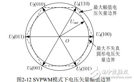
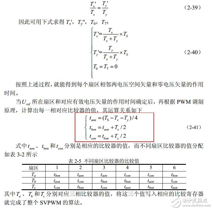
As shown in the figure, when the end of the composite voltage vector falls between the regular hexagon and the circumcircle, modulation has occurred, the output voltage will be distorted, and overmodulation must be taken. A scaling algorithm is used here. The vector that first occurs in each sector is defined as Tx, and the vector that occurs after that is Ty. When Tx+Ty≤TS, the vector endpoint is within the regular hexagon, no overmodulation occurs; when Tx+Tyâ€TS, the vector endpoint exceeds the regular hexagon and overmodulation occurs. The output waveform will be severely distorted, and the following measures are required:
When the end point of the voltage vector end point is pulled back into the inscribed circle of the regular hexagon, the two non-zero vector action times are Tx', Ty', respectively, and there is a proportional relationship:
Copper Tube Terminals Without Checking Hole
Our company specializes in the production and sales of all kinds of terminals, copper terminals, nose wire ears, cold pressed terminals, copper joints, but also according to customer requirements for customization and production, our raw materials are produced and sold by ourselves, we have their own raw materials processing plant, high purity T2 copper, quality and quantity, come to me to order it!
Copper Tube Terminals Without Checking Hole,Cable Lugs Insulating Crimp Terminal,Cable Connector Tinned Copper Ring Terminal,Tubular Cable Lugs Crimp Terminal
Taixing Longyi Terminals Co.,Ltd. , https://www.longyiterminals.com