The previous article mentioned that Mux inserts some control characters on data (TLP&DLLP) from the data link layer, as shown in the figure below. Of course, these control characters are only used for transmission between the physical layers. After the physical layer of the device at the receiving end receives these data, these control characters are removed and uploaded to its data link layer.
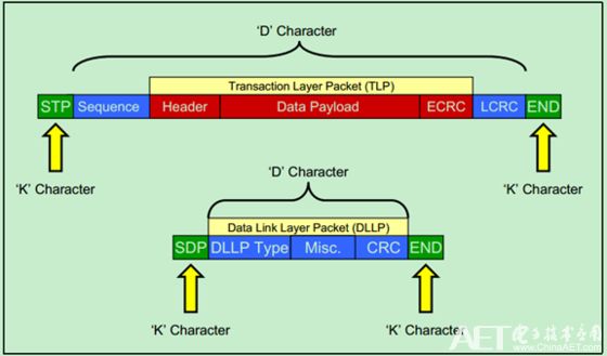
Of course, there are some other control characters besides STP, SDP, and END, such as EDB (described in detail in the previous article), SKIP, and COM. As shown below:
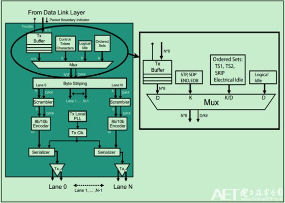
The previous articles mentioned Ordered Sets, which are mainly used for link training and so on. Each Ordered Set is DW-aligned (that is, four bytes), and the Ordered Set is also preceded by a K-character (control character) called Comma (COM), followed by some K-character or D-character (data character).
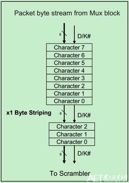
For a PCIe device with only one Lane, Byte Striping does not have any eggs. It is mainly used for data flow distribution of multiple Lanes. The x1 (one Lane) and x8 (8 Lane) examples are shown in the following two figures:

In addition, there are some other rules, mainly for Mult-Lane, that have no effect on a Lane:
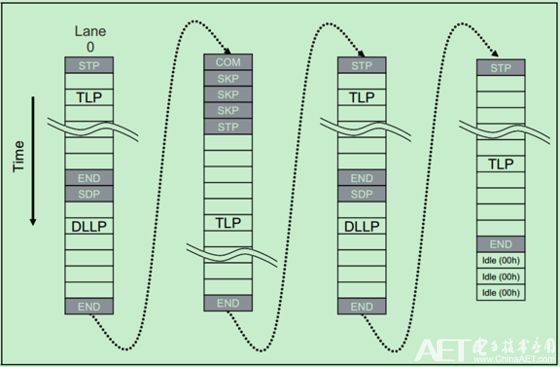
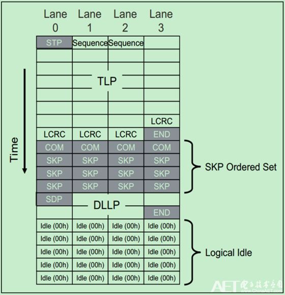
The x4 (4 Lanes) need to follow the following rules:
· STP and SDP characters are always sent on Lane 0.
· END and EDB characters are always sent on Lane 3.
· When an ordered set such as the SKIP is sent, it must appear on all lanes simultaneously.
· When Logical Idles are transmitted, they must be sent on all lanes simultaneously.
· Any violation of these rules may be reported as a Receiver Error to the Data Link Layer.
As shown below:
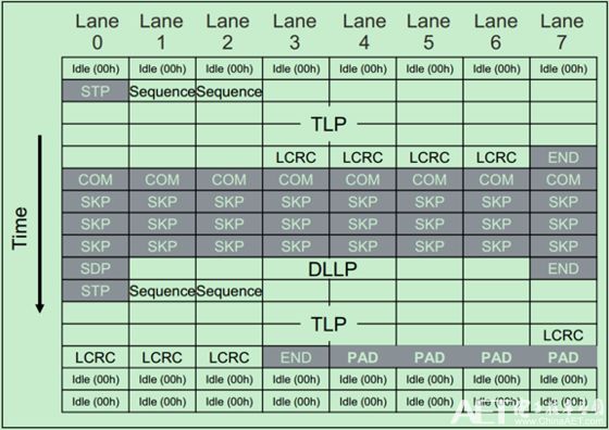
For x8, x16, x32 you need to follow the following rules:
· STP/SDP characters are always sent on Lane 0 when transmission starts after a period during which Logical Idles are transmitted. After that, they may only be sent on Lane numbers divisible by 4 when sending backâ€toâ€back packets (Lane 4, 8, 12, etc.).
· END/EDB characters are sent on Lane numbers divisible by 4 and then minus one (Lane 3, 7, 11, etc.).
· If a packet doesn't end on the last Lane of the Link and there are no more packets ready to go, PAD Symbols are used as filler on the remaining lane numbers. Logical Idle can't be used for this purpose because it must Appear on all Lanes at the same time.
· Ordered sets must be sent on all lanes simultaneously.
· similar, logical idles must be sent on all lanes when they are used.
· Any violation of these rules may be reported as a Receiver Error to the Data Link Layer.
An example of x8 is shown below:
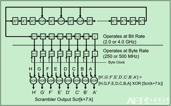
The sender's scrambler has a 16-bit Linear Feedback Shift Register (LFSR) that implements the following polynomial:

The specific functional block diagram is shown below:
Scrambler also needs to follow these rules:
· Different Lane scrambler must be synchronous operation;
The scrambler only acts on D characters (data characters) and logical idle characters (00H, Logical Idle) in TLP and DLLP, and does not affect K characters (control characters) and D characters in Ordered Set (such as TS1). TS2, etc.);
· Compliance Pattern Characters are not scrambled;
· COM characters (a control character that will not be scrambled) can be used to cause the LFSR in the scrambler at the sender and receiver to be initialized to FFFFH at the same time;
The scrambler is enabled by default, but PCIe Spec allows it to be temporarily disabled for testing purposes.
The K character (control character) used in PCIe is shown in the following table:

The corresponding 8b/10b encoding is shown in the following table:
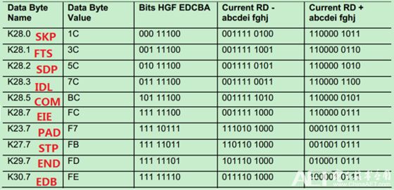
Note: Among them, the PAD character is mainly used in Mult-Lane. When the length of a packet is relatively short, some Lanes may not have data to send, and this time can be filled with PAD characters. As shown in the example of x8 in this article.
Ordered Sets are mainly used for the Link Management function. For Gen1 and Gen2 PCIe, all Ordered Sets begin with COM. Ordered Sets are sent synchronously on each Lane, ie each Lane will send the same Ordered Sets at the same time, so Ordered Sets can also be used for Lane De-skewing. In addition to link training, Ordered Sets are also used for Clock Tolerance Compensation and Changing Link Power States.
Correspondingly, there are mainly the following Ordered Sets: TS1 and TS2 Ordered Set (TS1OS/TS2OS), Electrical Idle Ordered Set (EIOS), FTS Ordered Set (FTSOS), SKP Ordered Set (SOS), and Electrical Idle Exit Ordered Set ( EIEOS).
Note: Detailed information on link management and Ordered Sets will be introduced in the follow-up blog post.
Board To Board Connector,0.5Mm Floating Connectors,0.5Mm Dual Slot Board-To-Board Connector,20P Board To Board Connector
Dongguan SOLEPIN Electronics Co., Ltd , https://www.wentae.com