1 Introduction
As a typical representative of the fourth generation of new energy-saving light sources, LEDs have the advantages of long life, energy saving, environmental protection, good color rendering and other unmatched light sources, and with the rapid development of high-power LEDs, they are more and more widely used in various A variety of areas such as indications, displays, backlights, general lighting, and urban night scenes. However, the light emitted by the LED light source is not uniform. Therefore, in the special occasion lighting where the illumination is strictly required, it is necessary to design a secondary light distribution structure according to the light emission characteristics of the LED itself and the expected light intensity distribution. Strong redistribution.
The light distribution structure generally has two kinds of reflective surfaces and lenses. At present, most of the secondary light distribution structures of LEDs adopt a lens structure. Considering that the lens has two transparent surfaces and a certain thickness, for any curved surface, if there is slight deviation in the design or manufacturing process, or if there is a little impurity in the lens, the refraction and energy distribution of the light will be great. Influence, and in practical applications, the lens has a high absorption rate of light and causes energy loss. The reflective surface is used as the secondary light distribution structure. In theory, only one reflective surface is needed, which is easy to process and has less energy loss, and better solves the problem of uniform illumination of the LED. This paper aims to design a reflective surface to perform secondary light distribution on the LED.
Conventional reflective surface light distribution structures rely on a combination of quadric or quadric surfaces with analytical solutions. However, for a light source with uneven illumination, a simple quadratic or quadric combination cannot achieve a specific light intensity distribution. In this paper, a free-form surface design method is used to establish a differential equation based on the illuminance characteristics of the light source and the expected light intensity distribution. The equation is solved by numerical solution method, and the free-reflection surface is fitted according to the solution result, and the result is performed by optical software. simulation.
2 reflective surface design
In this paper, a part of the light emitted by the light source directly illuminates the illumination surface, and another part of the designed reflection surface is reflected on the illumination surface, and finally a rectangular uniform illumination area is realized on the illumination surface. The relationship between the outgoing ray and the vector of the incident ray is obtained by using the law of reflection of light. Then the energy carried by the reflected ray is obtained by using the energy conservation and illuminance formula. Finally, the differential equation is listed, and a series of points for determining the free surface are obtained by solving the differential equation. , finally determine the required free surface.
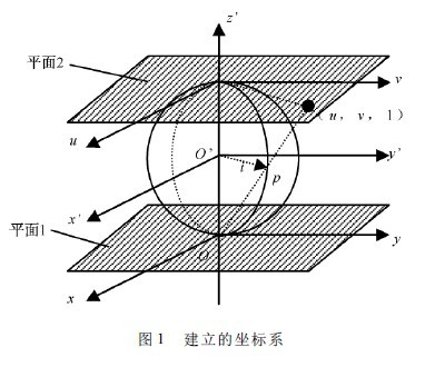
As shown in Fig. 1, o' is the position where the light source is located, and the coordinate system x'o'y' is established. 1 is the illumination surface. In order to make the calculation more convenient, the distance from the light source o' to the illumination surface 1 is unit length 1, and the center of o' is used as a unit ball, and the unit ball is tangent to the plane 1 at the o point. Plane 2 is a tangent plane parallel to plane 1 of the unit sphere. In plane 1 and plane 2, the x, y axis and the u, v axis are parallel to x', y', respectively. The origin of the z' axis is at o'.
If any light intersects the unit sphere at point p, then op is the unit vector, denoted as i. Connect o and p points and extend the intersection plane 2 at (u, v, 1), and set p point coordinates to (x', y', z'), then i = (x', y', z').
As shown, x' / u = y' / v = ( z' + 1) /2, and x'2 + y'2 + z'2 = 1,
It can be obtained: i = (1 + ω2 /4) ( u,v,1 - ω2 /4) , where ω2= u2 + v2.
2. 1 Law of reflection of light
As shown in Figure 2, I is the light emitted by the LED, incident on the q point on the reflective surface, R is the reflected light, reflected to the t point on the illumination surface, T is the vector from o' to t, and N is the reflection surface. The normal at the point q.
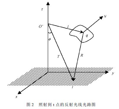
According to the law of reflection in non-imaging optical theory:
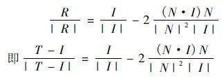
Where I = Ïi, the expression T = T ( Ï, u, v) of the vector T can be found. From the geometric relationship, the normal vector of the reflecting surface is the vector multiplication of two vectors in the tangent plane, that is, N = Au × Av = ( Ïi)u × ( Ïi)v .
It can be obtained from the i vector:

Bring the above three equations into the law of reflection and define p = Ïu,q =Ïv, and find T = T ( u,v,Ï,p,q), then the coordinates of the point at which the reflected light is reflected onto the illumination surface are
x( u,v,p,q) = uG + 2ÏpF,
y( u,v,p,q) = vG + 2ÏqF
among them

2. 2 Energy conservation
The LED illumination surface is perpendicular to the z-axis. This article uses a Lambertian LED light source. Part of the emitted light directly shines on the illumination surface, and the other part is reflected and then illuminates the illumination surface, creating a length and width on the illumination surface. A uniform illumination area for the rectangles of a and b. According to the conservation of energy, the radiant flux of the source should be equal to the radiant flux on the illumination surface.
The radiant flux radiated from the source onto the illumination surface is Φ1 =  The first term in the formula is the radiant flux directly incident on the illumination surface, Ω1 is the solid angle corresponding to the incident light of the portion, and the second term is the radiant flux reflected by the reflective surface onto the illumination surface, Ω2 is the portion The solid angle corresponding to the incident ray, and μ is the reflection coefficient of the reflective surface. The radiant flux received on the illumination surface is Φ2 = ∫ EdS, where E is the average illuminance on the illumination surface, and Φ1 = Φ2 according to the conservation of energy. Since the reflectivity of the reflecting surface can be as high as 95% or more, for the sake of simplicity, the reflection energy loss is not considered, and the illumination angle of the Langer-type light source is 120 degrees, then Φ1 =
  , Φ1 = Φ2, so E = πI0 /4ab.
There are two beams of light at point t, one is the T ray shown, and the other is the reflected ray of the I ray shown, E = E1 + E2, where E1 is the T beam produced at point t Illuminance, E2 is the illuminance produced by the B beam.
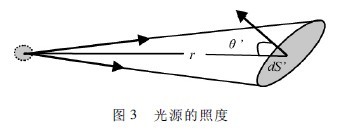
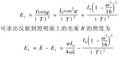
As shown in Fig. 3, if the luminous intensity of the point source is I, and the solid angle of the irradiated area element dS' is dΩ, the luminous flux irradiated on dS' is dΦ' = IdΩ = IdS'cosθ', Thus the illumination is E  Therefore, the illuminance of the light beam T directly irradiated on the illumination surface at the point t can be obtained as
2. 3 partial differential equation
During the reflection process, the intensity I of the incident light I and the illuminance E2 of the reflected light R to the point t satisfy the partial differential equation:
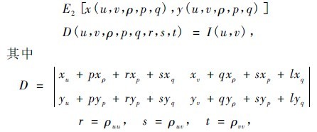
x and y are given by the results in 2.1. The intensity of the light I incident on the reflecting surface

E2 is given by the results in 2.2. Bring the above results into a partial differential equation and list the specific form of the partial differential equation.
The boundary conditions of the partial differential equation are determined by the illuminating characteristics of the Lambertian source and the rectangular uniform illumination area. First, the lower edge of the reflecting surface is also a rectangle with a length ratio of a: b, so that the light directly irradiated onto the illumination surface is a rectangular spot. The Lambertian LED source has an illumination angle of 120°, so the upper edge of the reflection surface is on a conical surface with a vertex angle of 120°. The above equation is discretized by numerical solution method to calculate partial differential equations. Set the initial point coordinates of the lower edge of the reflecting surface as the initial point condition, combine the boundary conditions, and bring it into the computer program to iteratively calculate the equation to find the coordinates of a series of points on the reflecting surface.