Think of the old adage called "Murphy's Law": "Everything that can go wrong will go wrong." Over the past 50 years, electronic component-based systems have been fully developed to provide very advanced monitoring and control functions with exceptionally high reliability. Worried about reliability is generally because of the potential danger to human life, followed by high losses caused by failures and decreased user satisfaction. However, things are never perfect, so there is always a need to constantly improve reliability to produce safe, durable electronic systems.
When system reliability must be guaranteed and there is no choice, the best but most expensive method is to use fully redundant circuits. The exact same circuit performs the same function at the same time, and some form of voting on the execution results always produces the safest effect. In many such systems, if a faulty circuit is detected, the circuit is automatically removed and replaced with an identical backup circuit. This is the ideal topology for long-term reliable operation. On the other hand, the consequences of failures do not always prove that the high cost of full redundancy is reasonable. Such systems rely solely on the inherent reliability of each component used. Failure of a single component can severely damage the system or permanently compromise accuracy. A design with this property assumes a large amount of risk, but can be implemented at the lowest cost.
In the case of highly reliable systems, the intermediate method is fault monitoring, in which the circuit monitors various system components and reports any anomalies. Since anything can happen at any time in the circuit, the more components that are monitored, the better. The response to the detected fault can vary from system downtime (eg, normally closed emergency stop switch on the train) to some simple service alarm (similar to the dashboard on the car). "Fool lamp") Wait.
This article explains how to improve the long-term reliability of a high-voltage lithium-ion battery pack by using the LTC6801 fault monitoring IC. In applications such as electric vehicles, uninterruptible power supplies, medical instruments, and even power tools, the use of batteries as a power source is an ongoing trend, each with varying degrees of reliability expectations.
Long-life battery power challenges
For electric vehicles and a large number of other types of portable devices, batteries have become a major non-traditional energy source. Lithium-ion batteries are very popular because the energy density of lithium-ion batteries allows lithium-ion batteries to be smaller and lighter than batteries of other chemical compositions with the same energy density. For high-power applications, such as electric vehicles, it is necessary to stack hundreds of batteries to form a high-voltage power supply that produces less current and uses thinner and lighter wires. In this type of automotive application, the safety of the driver is the first, followed by the satisfaction of the owner. Therefore, there are obvious reasons for achieving safe and reliable long-term operation. To achieve this, the power of each battery must be continuously monitored to maintain an optimal level for years of use.
In the simplest case, the circuit is required to measure the voltage of each cell in the battery pack. This measurement is typically performed by an AD converter that passes the information to a microcontroller. The controller carefully manages the charging and discharging of all batteries so that the battery does not operate beyond a tight range, and exceeding this range can greatly shorten battery life. In the case of a system with hundreds of individual cells, an integrated measurement circuit can save a significant number of components. The LTC6802 from Linear Technology is such an integrated functional component. With a built-in 12-bit ADC, it can measure and report voltages on up to 12 cells and two temperature sensors. Any number of batteries can be stacked on top of each other, and each set of measured voltages consisting of 12 batteries is serially transferred to a main microcontroller. These measurement devices and controllers form the heart of the battery management system.
Careful control of the state of charge of each cell is extremely important to extend the usable life of the battery, but this may not be enough to satisfy the increasingly demanding automotive customers. In the case of sensitive electronics, the car presents a harsh and dangerous operating environment. To achieve long-term satisfaction without worry, it is necessary to conduct a “what-if†analysis of the system. A few issues to consider are perhaps:
What happens if one wire that connects the battery is disconnected?
What happens if the voltage measurement accuracy shifts?
What happens if the internal register bits remain at a certain value and always indicate a good battery voltage reading?
What happens if the measurement IC is somehow damaged by a severe system voltage transient?
The most latent problem may cause the controller to erroneously determine that a battery or a battery pack is in perfect condition, and the fact is that the battery or battery pack is not measured in the correct way. Afterwards, these batteries may be completely discharged or dangerously overcharged, but the system is not aware of it at all. Need something to "monitor the monitor" to achieve a higher level of reliable operation.
Battery Management System (BMS) Fault Monitoring with the LTC6801
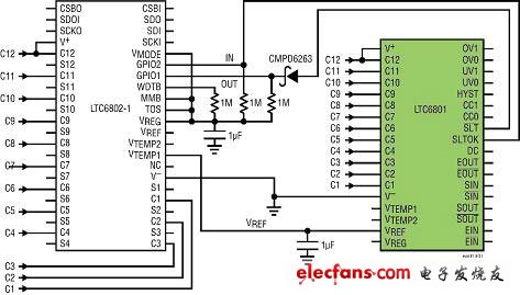
An alternative to the fully redundant measurement method is to connect the fault monitoring circuit in parallel with the measuring device to function as a basic function of the review system. The circuit in Figure 1 shows a solution for a battery pack consisting of 12 lithium-ion batteries using an LTC6802 measuring device and an accompanying LTC6801 fault monitor.

Figure 1: Combining battery measurement and fault detection to improve reliability.
The LTC6802 provides accurate measurements, while the LTC6801 checks the overvoltage/undervoltage condition of each cell. The LTC6802-1 becomes the primary electronic component in the system by measuring and reporting the voltage of each cell in accordance with the instructions and applying a discharge current to the battery to distribute the charge per cell. Data is transferred to the controller over the SPI serial data link. At the same time, the LTC6801 also monitors each battery in the battery pack. Without the intervention of the system controller, the LTC6801 can periodically sample the voltage of each cell and perform simple undervoltage and overvoltage comparisons. If all conditions are normal, the LTC6801 provides a differential clock signal on the Status Output line. If anything is wrong, then the clock stops. As for the nature of the problem, the LTC6801 does not provide any information because it simply indicates that something is incorrect. Once this clock is stopped, the controller can perform diagnostics to determine what is going wrong.
Far more than a simple comparator
The LTC6801 is designed with careful consideration of many potential system failures and is also easy to use. An important design requirement is to allow the device to operate automatically without any software. The only external requirement is the power supply (provided by the battery pack itself) and an enable clock signal. Without the clock input enabled, the LTC6801 stays in a static low power state, drawing only a few uA of current from the battery pack. The enable clock can be provided by a system controller or any other source of oscillation such as the LTC6906 silicon oscillator. Upon receipt of the clock signal, the device automatically wakes up and begins monitoring all of the batteries.

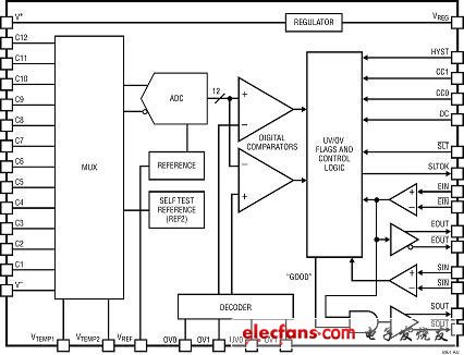
Figure 2: The internal circuitry of the LTC6801 provides not only simple comparator functionality
REGULATOR: Voltage Regulator
MUX: multiplexer
REFERENCE: Benchmark
SELF TEST REFERENCE: Self-test benchmark
DIGITAL COMPARATORS: Digital Comparator
DECODER: Decoder
UV/OV FLAGS AND CONTROL LOGIC: UV/OV Marking and Control Logic
"GOOD": "Good"
Figure 2 is a block diagram of the basic components of the LTC6801. A 12-bit delta-sigma AD converter (ADC) filters and digitizes the voltage of up to 12 cells and two temperature sensors. A 5V regulator and a precisely trimmed 3V ADC voltage reference are built in. All operating characteristics of the device are set by bonding the device pins to a 5V regulator, 3V reference, or V-. No external components are required.

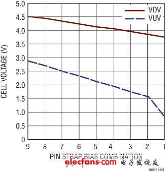
Figure 3: Battery voltage alarm threshold selection is set by pin overlap.
Cell Voltage Thresholds: Battery Voltage Threshold
Cell Voltage: Battery voltage
Pin Strap Programming Voltage CombinaTIons: Pin lap setting voltage combination
Figure 3 plots the settable overvoltage and undervoltage thresholds. The overvoltage (OV) threshold is chosen to use a Li-Ion battery with a 3.3V nominal voltage and a 4.2V alarm level, while an undervoltage (UV) threshold provides a reasonable indication of battery drain. The OV and UV thresholds are set by different pins, so any combination is possible. The OV and UV levels must be set to indicate that something may be wrong when not too close to the normal battery voltage, otherwise it may cause an annoying jump in the fault detection circuit.
It is also possible to set a fixed hysteresis of up to 500mV for these thresholds. It is useful to set a fixed hysteresis when the detected fault-triggered action may cause a voltage change on the battery, such as immediately disconnecting the load from the battery pack. Hysteresis prevents jumps and jumps out of the fault state.
Like to play games for the computer configuration,Gaming Keyboard have certain requirements,mouse as one of the most important accessories,is also very important.While Wireless Gaming Mouse is fine,there are still friends who find the delay and charging a hassle and prefer a wired mouse.Compared with the wireless mouse in business office portability. Wired mouse is more suitable for esports games,whether in terms of transmission delay or anti-interference ability convenient wired mouse is stronger than wireless mouse. Therefore, it is essential to choose a suitable wired mouse for those who often play esports games.
Playing games are generally selected cable mouse, cable mouse data transmission is stable,perfect,playing games do not have to worry about losing frames.The Wired Gaming Mouse has a huge advantage in stability because it is directly connected to the computer with a wire, so it has little interference from the outside world.More suitable for the mouse operation requirements of the game and design use. Wired mouse also has some disadvantages,such as can not operate too far, can only be used in the vicinity of the chassis (mouse wire length is limited).In addition,due to the cable, it will be a little messy feeling, and its disadvantages are summarized as follows. It drags and drags and feels uncomfortable to use, which is inevitable unless you have to use a wireless mouse.Use distance is short.This also can't be done.But if you don't think the mouse cable is troublesome, now there is a USB extension cord to sell, as long as you want.

Wired Gaming Mouse,Led Wired Gaming Mouse,Wired Optical Gaming Mouse,Both Wired And Wireless Mouse
Henan Yijiao Trading Co., Ltd , https://www.yjusbhubs.com