With the development of power electronic device technology, high-power devices are developing rapidly in the fields of rail transit, direct current transmission, wind power generation, etc. Among them, the performance of IGBT devices is particularly prominent. In specific application conditions, each IGBT module needs A dedicated driver, IGBT driver has a significant impact on the operating performance of the IGBT
The traditional IGBT driver technology realized by analog circuit is mature and stable, but since the parameters of its driver are mostly implemented by hardware, the parameter adjustment is more complicated. Different types of IGBTs must be designed with different drivers. Control, you can flexibly modify the software parameter settings of the driver to adjust the performance of the IGBT. For different IGBT models, only different drivers need to be loaded, which can solve the model matching problem of the traditional driver products.
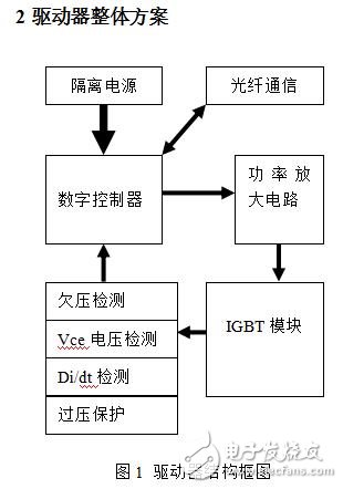
As shown in Figure 1, the driver mainly includes: high-level isolated power supply, optical fiber communication interface, power amplifier circuit, detection and protection circuit, digital controller and other five parts.
2.1 high-grade isolated power supply
In the design of high voltage IGBT driver, power supply design is one of the key parts. The output power of the power supply determines the operating frequency that the IGBT can use in actual operation. If the output power of the power supply is insufficient, the undervoltage may occur when the IGBT device operates at high frequency. Phenomenon, resulting in increased IGBT losses, and even IGBT damage.
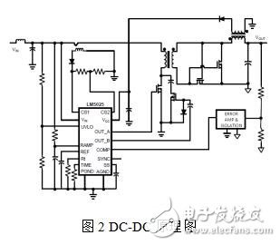
In this design, TI's LM5025 chip is used to design the flyback DC-DC circuit (see Figure 2 for the circuit diagram). The primary in the circuit has a current-sense soft-start function. When the voltage drop across the current-sense resistor reaches 0.25V, the power supply Plays a good overcurrent protection.
2.2 Optical fiber communication interface
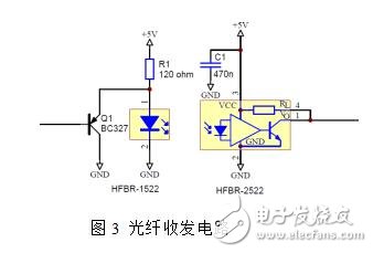
In the interface design of the communication of the user's main control system, the optical fiber communication with strong anti-interference ability is selected to prevent the control signal from being erroneously triggered by the interference. The fiber is HFBR-1522, HFBR-2522, and the fiber circuit is shown in Figure 3.
2.3 power amplifier circuit
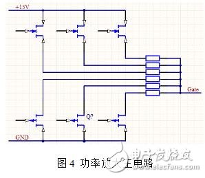
The mosFET with very low on-resistance is selected as the switching device to form the IGBT gate power output circuit, as shown in Fig. 4. At the same time, multiple gate resistance switching modes are adopted to realize the adjustment of the IGBT performance under different conditions. When the IGBT is normally switched, the switching speed of the device can be controlled by adjusting the gate resistance to optimize the efficiency of the device. When the IGBT is working abnormally (for example, short circuit), the operating state of the device can be controlled by adjusting the gate resistance to prevent device damage and achieve the purpose of protecting the device.
2.4 detection protection circuit
In order to prevent any abnormal faults in the operation of the IGBT device, the driver needs to detect the state parameters of the IGBT. If an abnormality is found, the driver automatically takes a protection action and notifies the master.
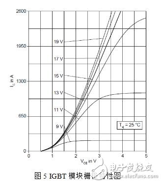
Undervoltage detection: At present, each IGBT manufacturer recommends that the gate voltage of the IGBT device be ±15V (the maximum voltage withstand voltage is ±20V). If the IGBT device is less than 15V during operation, the saturation voltage drop according to the IGBT device. The relationship between VCE and gate voltage (as shown in Figure 5), as the gate voltage drops, the IGBT saturation voltage drop will increase, resulting in increased IGBT device losses, which may damage the device. Therefore, the gate must be output to the driver. The voltage is tested and the drive is protected immediately if an undervoltage condition occurs. At the same time, it should be noted that the short-circuit current of the IGBT is proportional to the gate voltage. Therefore, when the device is turned on, the gate appears to be higher than +15V. If the device fails, a short-circuit current will occur larger than the normal operating condition. Therefore, the driver must ensure the gate. The pole turn-on voltage is within a reasonable range.
Vce voltage detection: Vce voltage detection can provide IGBT device parameters for the digital controller. The controller can judge the working state of the IGBT through the Vce voltage, and adopt corresponding strategies to control the IGBT differently.
Overvoltage protection: During the turn-off of the IGBT device, due to the parasitic inductance of the bus loop, the turn-off voltage will generate a voltage overshoot spike, and the overshoot amplitude is ΔV=Ls*di/dt. If the spike voltage exceeds the IGBT The rated voltage of the device, the IGBT device will be broken down, causing device damage.
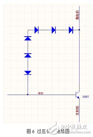
The overvoltage protection circuit adopts a method in which the TVS tube and the current limiting resistor are connected in series, and the collector is connected to the gate (as shown in FIG. 6). When the shutdown occurs, the collector exceeds the set value (the set value is smaller than the IGBT rating). When the voltage spikes of the value), the TVS tube is reverse-conducted, and a current is injected into the gate through the current limiting resistor to slow down the IGBT turn-off speed (reduce di/dt), thereby achieving the purpose of limiting the voltage spike. The user selects the appropriate number of TVS tubes and a single TVS breakdown voltage parameter according to the specific application conditions.
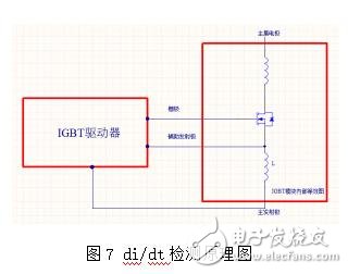
Di/dt detection: (as shown in Figure 7), the internal equivalent diagram of the IGBT module can be seen. Because of the parasitic inductance between the main electrode loop and the auxiliary electrode loop of the internal link of the IGBT module, the main current IC is working when the IGBT module is working. Inflow from the main electrode, after the parasitic inductance L flows out, according to the induced voltage V=-L*di/dt, it can be seen from the formula that the induced voltage V value is proportional to the di/dt value, which is generated by detecting L. The induced voltage can obtain the di/dt value of the main current Ic. During the operation of the IGBT module, if the induced voltage is higher or lower than the set value, the device di/dt is considered to be in an abnormal state, protection is required, and a di/dt fault is reported to the main control system.
Digital controller function
The digital controller mainly performs control of the power amplifying circuit according to the input signal to drive the IGBT device. At the same time, the working state of the IGBT device is determined according to the feedback signal of the detecting circuit, and if an abnormal condition occurs, the IGBT device is immediately protected according to the setting strategy.
4 driver level test
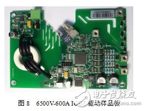
In order to determine the correctness and feasibility of the basic functions of the driver stage, the sample board of Figure 8 is used for testing. The test sample is a 3300V-1500A IGBT module, and the general-purpose double pulse test method is used. The test waveform is shown in Fig. 9.
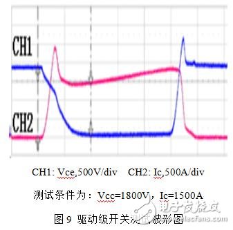
It can be seen from the above test results that the driver board can safely turn on and off the IGBT module under test conditions.
5 Improve direction
The digital IGBT driver proposed in this paper adopts the TVS tube series connection in the overvoltage protection detection, which can only have a good effect on the parasitic overvoltage generated by the di/dt in the IGBT device shutdown, but this method also exists. Disadvantages, if the user's threshold setting for overvoltage protection is unreasonable, and the system will have more overvoltage during operation, or a longer overvoltage, the IGBT device will be damaged by high voltage at the gate, or it should be The turned-off IGBT is passively turned on, and the upper and lower tubes are short-circuited, damaging the upper and lower tubes IGBT. Therefore, the Vce detection circuit can be added to detect the collector voltage in real time and formulate a protection strategy.
Push Wire Connectors,Custom Push Wire Connectors,Push In Connector,Quick Wire Connectors
Jiangmen Krealux Electrical Appliances Co.,Ltd. , https://www.krealux-online.com