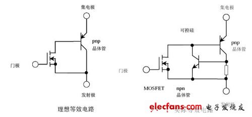
IGBT, the Chinese name is insulated gate bipolar transistor, it is a device composed of MOSFET (input stage) and PNP transistor (output stage), which has the characteristics of small driving power and fast switching speed of MOSFET device (control And response), and the characteristics of bipolar devices with reduced saturation voltage and large capacity (the power stage is more durable), the frequency characteristics are between MOSFET and power transistor, and can work normally in the frequency range of tens of kHz.
The ideal equivalent circuit and the actual equivalent circuit are shown in the figure:

The static characteristics of IGBTs are generally not used and need not be considered for the time being, focusing on the dynamic characteristics (switching characteristics).
The simple process of dynamic characteristics can be obtained from the following tables and graphics:

IGBT opening process
IGBT is divided into several periods in the process of opening
1. The turn-on process similar to MOSFET is also divided into three stages of charging time
2. Only in the late stage of the drain-source DS voltage drop process, the PNP transistor adds a delay time from the amplification region to the saturation process.
In the above table, it defines: the turn-on time Ton, the rise time Tr and Tr.i
In addition to these two times, there is also a turn-on delay time td.on: td.on = Ton-Tr.i
IGBT is off
During the turn-off process of the IGBT, the waveform of the drain current becomes two stages.
The first paragraph is based on the characteristics of the MOS tube shutdown
The second stage is that after the MOSFET is turned off, the charge stored on the PNP transistor is difficult to discharge quickly, resulting in a longer tail current for the drain current.
In the above table, the off time Toff, fall time Tf and Tf.i are defined
In addition to the table, trv is also defined as the rise time of the DS terminal voltage and the turn-off delay time td (off).
The falling time of drain current Tf is composed of t (f1) and t (f2) in the figure, and the total off time can be called toff = td (off) + trv ten t (f), td (off ) The sum of + trv is also called storage time.
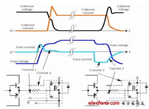
The detailed relationship between gate current and gate voltage, CE current and CE voltage can be seen from the figure below:

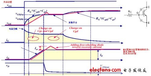
A closer look at the characteristics of the gates of MOS tubes and IGBT tubes from another picture may have a clearer concept:
Opening process

Shutdown process

With the development of the times, the consumption level of people is gradually increasing. At the same time, people's entertainment methods are beginning to diversify, especially for modern young people. As a result, different kinds of electronic products are starting to be in people's lives, and the booming Electronic Cigarette industry reflects this.
Described including the upper shell, the upper shell at the top of the smoke outlet, as described in the bottom of the upper shell with airway, described with the smoke outlet in the airway and also to match the upper shell, the lower part of the shell described the airway in the direction of the lower shell extension, as described in the lower shell near one end of the upper shell is equipped with oil mouth, described the lower shell with batteries, described at the bottom of the bottom shell has come in The air port is provided with an oil storage bin in the lower shell, and the air passage passes through the oil storage bin and is provided with a heating atomization bin at one end away from the smoke outlet. The utility model has beneficial effects: it can meet the smoking habit of different users, avoid the premature end of the use experience caused by excessive consumption of smoke oil, and indirectly prolong the service time and life of the product.
Refillable E-Cig Oem,Refillable Vape Pod,Refillable Vape Pen Oem,Refillable Mod Oem
Shenzhen MASON VAP Technology Co., Ltd. , https://www.disposablevapepenfactory.com