Download URL: https://, select Quartus II Web Edition, ModelSim-Altera Starter Edition. At present, these two software are free of charge, do not require a license, installation is simple, the use period is 30 days.
[Note] Be sure to remember the installation path, especially the ModelSim-Altera installation path.
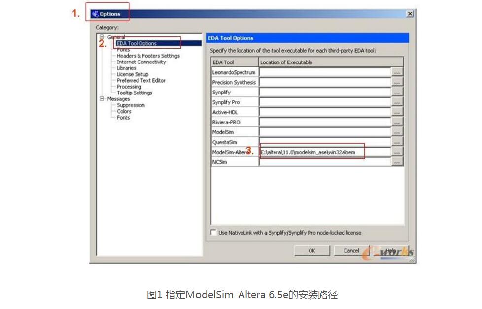
Open Quartus II 11.0 software, create new projects and files and save them.
1. Then select tools->options in the menu bar;
2. Select EDA tool options in the options tab;
3. In the tab, the following ModelSim-Altera one specifies the installation path as E:/Altera/11.0/modelsim_ae/win32aloem (where E:/Altera/11.0/modelsim_ae/ is the installation of ModelSim-Altera 6.5e on my computer. path)
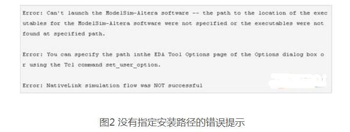
[Note] If ModelSim-Altera 6.5e installation path is not specified, the following error message will appear when calling ModelSim-Altera:
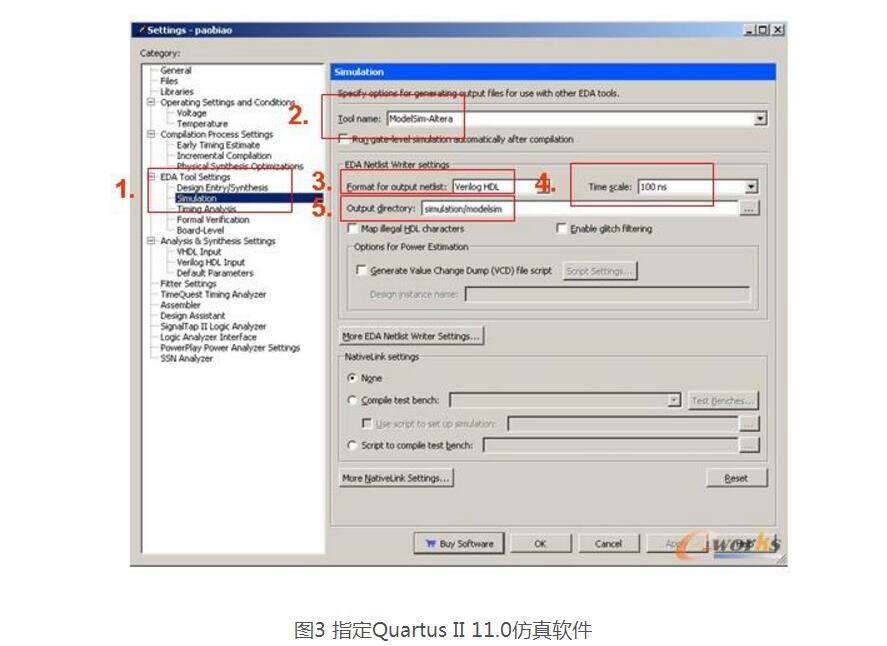
Select Assignments-"Settings" in the Quartus II 11.0 interface menu bar.
1. Select Simulation in the EDA Tool settings under the interface.
2. Model Name select ModelSim-Altera;
3. Format for output netlist Select the type of development language Verilog or VHDL, etc.
4.Time scale specifies the time unit level
5.Output directory specifies the output path of the test file template (this path is the relative path of the project file).
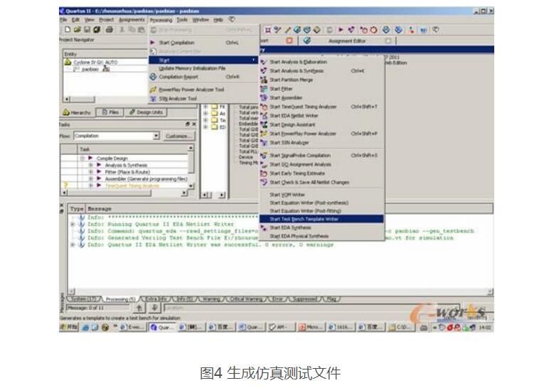
Select Processing-Start-Start Test Bench Template Writer under the menu bar of the Quartus II 11.0 development interface. The prompt is generated successfully.
Open the simulation test file (find the file with the suffix “.vt†in the Output directory directory specified in 3 above) and edit it according to your own needs.
1. In the Quartus II 11.0 interface menu bar, select Assignments-"Settings-"EDA Tool settings-"Simulation;
2. Select Test benches to the right of the Compile test bench;
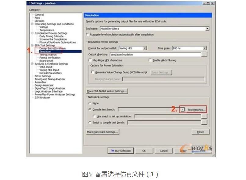
3. Then select New in the interface that appears. In the newly appeared interface, enter the name of the test file in Test bench name. Enter the top-level module name in the test file in the Top level module in test bench field.
4. Select Use testbench to perform VHDL timing simulation and enter the design test file in Design instance name in testbench. The default designation name is i1;
5. Then select the test file in the file name under the Test Bench Files column (the test file with the suffix “.vt†in the output path of the test file specified in step 3), then click add, step by step OK.
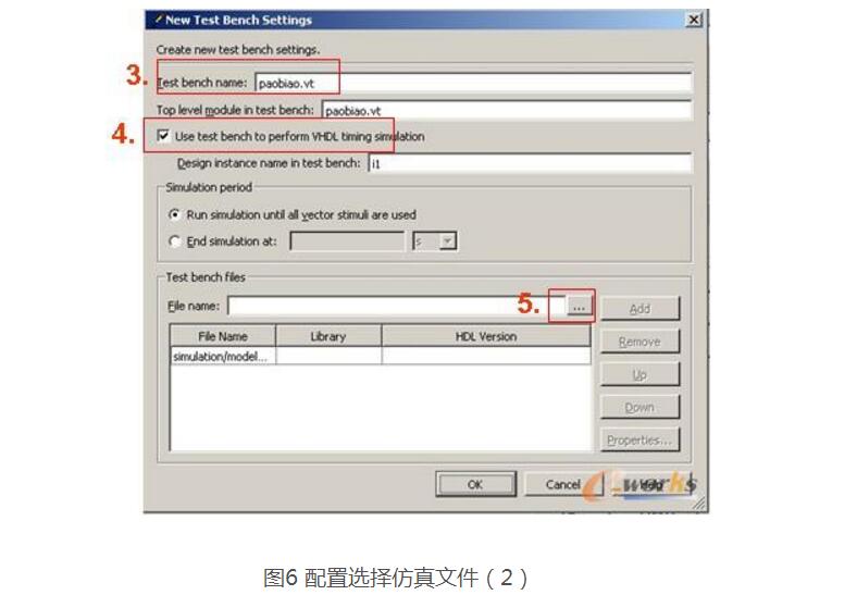
[Note] The Test bench name and Top level module in test bench and the Design instance name in test bench are the file names of the ".vt" file, the top-level entity module names in the vt file, and the instantiation names of the modules in the Verilog or VHDL file.
Six, after the simulation file configuration is complete, return to Quartus II 11.0 development interfaceIn the Quartus II 11.0 interface menu bar, select Run EDA Simulation Tool -> EDA RTL Simulation in the menu bar to perform the behavioral level simulation. Next, you can see the operation interface of ModelSim-Altera 6.5e and observe the simulation waveform.
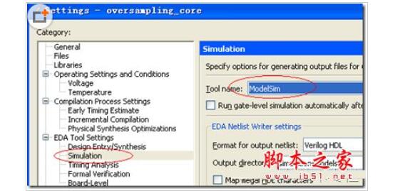
Quartus II calls modelsim seamless simulation detailed graphic tutorial1. Set up simulation tools
Assignmentèsettingè EDA tool settingèsimulation Select the tools you need.
2. Automatically generate test stimulus file template:
processingèstartèStart test bench template writer
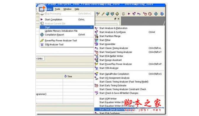
After we click on the system will automatically generate a test stimulus file xxx.vt (Verilog test bench) or xxx.vht (VHDL test) in the directory: current folder è simulation è modelsim (this folder name is related to your selected simulation tool). Bench), the file name is the same as the name of the Top module in your project, the suffix is ​​.vt or .vht.
3. Edit the generated test bench file
We add the incentives and initialization statements we need. Here we also need to change the name of the test bench module to tb (we will see that this name is associated with the following settings).
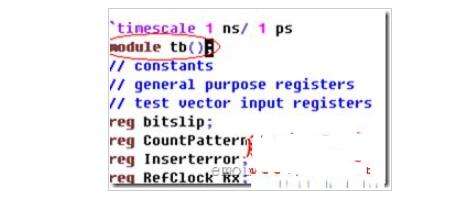
4. Connect the test bench, we need to call the simulation tool automatically from Quartus, so you need to set the Native Link option.
a) In the simulation setting page, set the settings in the Native Link dialog box. We are selected here because we need tools to automatically invoke incentives
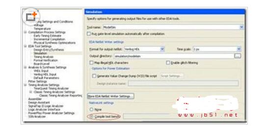
b) Click Test Benches on the right. We need to set an associated test bench here.
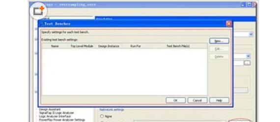
This will bring up a dialog box that lets you specify the test bench, because we did not specify any test bench before, so this is blank.
c) Specify test bench
Since we are producing the test bench for the first time, click new.

Click New to generate a New Test bench setting dialog where you bind the test bench to your corresponding test bench file.
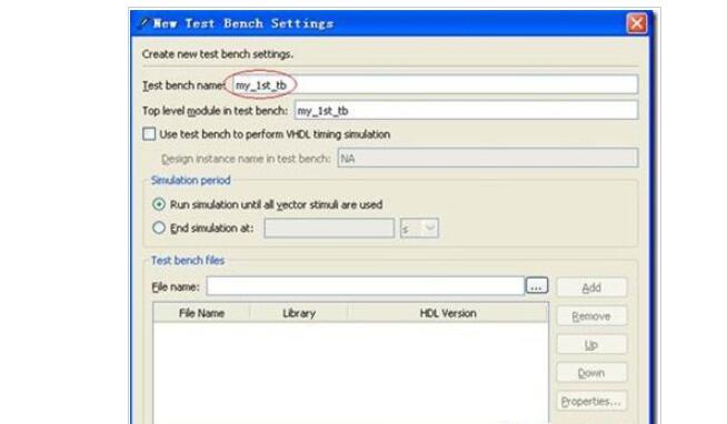
Here we enter a name "my_1st_tb" in the Test bench name dialog box. We will see that "my_1st_tb" is also automatically displayed in the following Top level module in test bench dialog. Note that this name should be consistent with the module name in your test bench. We used to change the test bench module name to tb in step 3, so we should change the name of the dialog box to tb.
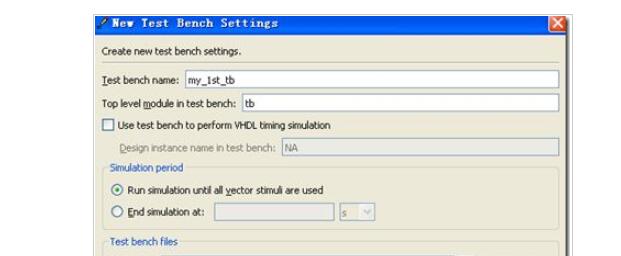
d) Join the test bench file
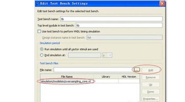
5. Perform simulation
When these settings are complete, select the menu
toolèRun EDA Simulation toolèEDA RTL simulation

You can directly call modelsim for simulation.
6. Tips:
We call this simulation, if it is Modelsim AE will not compile lib file each time, but if we use the Modelsim SE version, each call will need to recompile the library, very unhappy, here we recommend that you modify the script file, simulation .
a) When we run the simulation as described above, we stay in the Modelsim interface.
b) On the command line of the Modelsim interface, we click the up arrow key and we will see the previous instruction. We can see that
Do xxxx.do This shows that the tool executes the previous command xxxx.do script file, our example here is
Do oversampling_core_run_msim_rtl_verilog.do
i. We know the script that the tool executes, and we can change this script as we see fit. Use the edit oversampling_core_run_msim_rtl_verilog.do command to see the contents of this script (Of course, we can use Ultra Edit or VIM and other text editing software to open this script file). This script is usually divided into 3 parts of the library file compilation section, design file compilation, operation parameter setting and start execution section
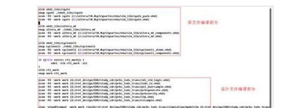
Ii. Usually, the library file needs to be compiled only when it is first compiled. Later, we only need to specify the location of the library file in the simulation. We do not need to compile it every time. So we can comment out "library file compiling part". The part in the red box in the following figure is the compile part of the library that is commented out. This will save our simulation time. Note that # is a comment in the scripting language.
Iii. We will save the edited script file as sim.do. In the future simulation, we can run do sim.do directly in the script on the Modelsim command line (Of course, we need to first change the working directory of Modelsim to the project. Folder/simulation/modelsim/).
c) In addition, the waveform file generated by another script is usually the top layer of the test bench is added to the graphics screen. We can see the third part of the script (operation parameters and start execution), the default imperative
Add wave *, This command is to add all the letters on the top of the test bench to the wave window.
For us, during the debugging phase, there are many low-level signals that we want to observe, so we need to manually modify the command.
i. In the modelsim window, select the module you want to care about. Right click to add the signal you are interested in to the waveform
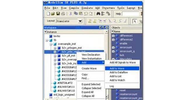
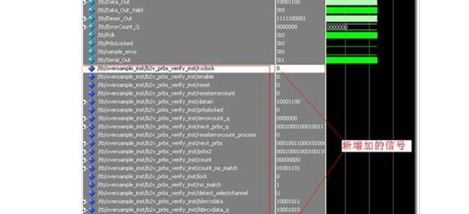
Ii. At this point we can save the waveform format in the wave window. Click on the file file in the wave window... Select the file name wave.do.
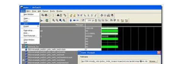
Iii. In the script we executed, add wave *, this command is replaced by do wave .do, you can automatically add the waveform you want to observe every time you execute the simulation.

7. Next, the last question is how to compile a library file once and let the software not compile every time. Actually, altera has prepared corresponding options for customers, but it is hidden deeper and harder to find.
a) One-time compilation library:
i. Click toolè launch EDA simulation Library Compiler

Ii. We will see a page that lets us select the device. According to your actual situation choose the following settings. Click start compile, the software will automatically help you complete the compilation, and then turn off just fine, so you should have completed the compilation of the library.
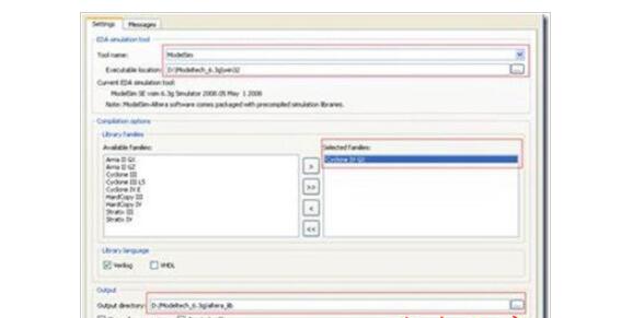
Iii. Next we need to make some changes in the QII simulation settings page.
We need to go back to the settings interface
Assignmentèsettingèsimulationèmore Nativelink setting
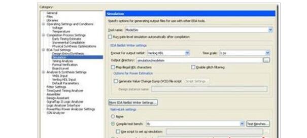
Set the appropriate path.
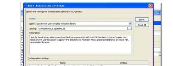
Well, rerun the simulation and you will find that we will not compile our library file anymore.
eSky 4G GPS Trackers supports Cat-1, Cat-4, Cat-M and NB-IoT. Tracking, geofence, backup battery, Over speed limit, 3-Axis Accelerometer, Storing Message, Low Voltage Detection, Power Saving Mode, Expand Other Peripherals, and OTA (Over the Air) are all the basic features. We also have trackers with upscale features like fuel, temperature monitoring and with RS232, RS485. These are Robust and affordable vehicle tracking device with inputs/outputs, remote immobilization for fleet management, driver ID, driver safety and behavior monitoring, theft recovery, and more.
All Kinds of 4G Cat-M Vehicle GPS Tracker, there must be one which should meet your expectation.
CAT-M vehicle GPS Trackers,CAT-M car GPS Trackers,Waterproof vehicle GPS Tracker, IP65 vehicle GPS Tracker,OBDII CAT-M vehicle GPS Trackers,Wireless CAT-M GPS Trackers
eSky wireless Inc , https://www.eskygpsiot.com