Through the research and development of the robot's mobile function, this article has developed various mobile mechanisms to meet the different requirements of various working environments. The omni-directional wheel can achieve high-precision positioning, in-situ adjustment of the attitude and any continuous trajectory movement in the two-dimensional plane, and has the unique characteristics that can not be replaced by a general wheel-type movement mechanism. It is important for studying the free movement of mobile robots. Comprehensive analysis of the existing mobile robot movement mechanism, movement characteristics, analysis of its kinematics characteristics; proposed a mobile robot static walking stability determination method, planning the robot linear walking gait, fixed-point turning gait, and over the obstacles The walking gait of the object; and the use of PLC to control the gait.
This paper first introduces the main features of the servo motion control system, and then introduces the working principle of the servo motion control system. Finally, the robot is introduced in detail from three aspects: the selection of the robot movement mode and the structural design, the mobile robot motion control system and the robot control system design. Servo motion control system design, follow the small series specifically to understand.
(1) Accurate detection device: Closed-loop control with composition speed and position.
(2) There are multiple feedback comparison principles and methods: According to different principles of information feedback implemented by the detection device, the method of feedback comparison of the servo system is not the same. At present, there are three kinds of pulse comparison, phase comparison and amplitude comparison.
(3) High-performance servo motors (servo motors for short): CNC machines for high-efficiency and complex surface machining. Servo systems will often be in frequent starting and braking processes. The ratio of the output torque to the moment of inertia of the motor is required to produce a sufficiently large acceleration or braking torque. The servo motor is required to have a sufficient output torque at a low speed and run smoothly so as to minimize the intermediate links in the connection with the mechanical movement part.
(4) Speed ​​adjustment system with wide speed range, ie speed servo system: From the control structure of the system, the position closed loop system of CNC machine tools can be regarded as a double closed loop automatic control system in which the position is adjusted to the outer ring and the speed is adjusted to the inner ring. The actual working process of the system is to convert the position control input into a corresponding speed reference signal, and then drive the servo motor through the speed control system to achieve the actual displacement. The main movement of CNC machine tools requires higher speed control performance, so the servo system is required to be a high-performance, wide-speed control system.
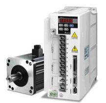
Servo motion control system working principleThe servo control system is actually a kind of feedback control system that realizes fine control of the mechanical working process, and is mostly used to control the motion vector of the machine. Servo control system can be divided into hydraulic servo system, pneumatic servo system and electromechanical servo system according to the type of drive components used. The first two features are obvious, but there are some limitations in the scope of application. The energy of the electromechanical servo system is electric energy that can be used in the most convenient and flexible way. Its driving element is a motor that can be designed and selected according to various specific requirements, and can achieve the most excellent system performance, thus becoming the most widely used server system.
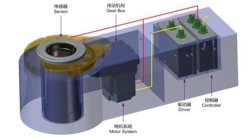
The electromechanical servo control system takes the motor as the control object, the controller as the core, the power electronic power conversion device as the executing mechanism, and the electric drive automatic control system formed under the guidance of the automatic control theory. This type of system controls the torque, speed, and rotation angle of the motor, converts electrical energy into mechanical energy, and achieves the mechanical motion requirements. Depending on the load imposed by the motor, the servo system can be used in many applications such as defense, industrial, and civilian applications, such as: radar scanners for the defense industry, photoelectric tracking followers, fire control systems, measurement and control systems, and high-level simulations. Precision turntables, servo load simulators, etc.; automated production lines, machine tools, robotic arms, monitoring equipment turntables, etc. in the industrial field.
Detailed Design of Robot Servo Motion Control System Based on PLCI. Selection and Structural Design of Robot Movement Methods
1, the choice of mobile mode
The current mainstream mobile methods are basically wheeled, legged, and tracked. However, due to their respective advantages and disadvantages, current scientists are increasingly pursuing the improvement of comprehensive performance. The wheel-type moving mechanism has the advantages of fast movement speed, high energy utilization rate, simple structure, convenient control, and can draw on well-established automotive technologies, but the off-road performance is not very strong. Although the leg-type mobile structure has good off-road capability, it has a complex structure and low efficiency. The crawler type is mainly due to heavy tracks and a large number of drive wheels, making the overall structure bulky and consuming relatively large power.
The environment for this design is mainly man-made and the terrain is relatively flat. However, obstacles such as stairs and stairs need to be taken into consideration. Therefore, I intend to design a combination of wheel and leg movements to use wheeled structures on flat roads with high efficiency. , Quick and so on, in the need to go up the stairs, up stairs and other places using leg-type structure for obstacles. Because the robot has a leg-type structure and requires steps and stairs, a four-leg structure is adopted because although a stepped structure can satisfy the requirements even for a wheeled structure, it is not good for climbing a stair wheel structure, so a leg is needed. With the existence of the structure, stairs can be seen everywhere in life. If the robot is to have a good environmental adaptability, it is necessary to overcome the stairs. I decided to choose a four-legged structure, and the basic structure is shown in Figure 1. The middle is the robot body, which has the robot control system and the motor that drives the upper limbs. The ends of the limbs are tires. Each leg of the robot is divided into upper and lower limbs, and the middle part is the joint, and the lower limbs can rotate around it.
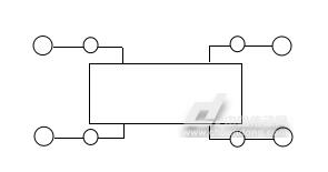
Figure 1 The basic structure of the robot
2, the concept of robot movement principle
Because the environment is better, it basically belongs to the flat ground. Therefore, the main way of moving is wheel-type movement. The leg-type structure is only used when there is a need to go up stairs or stairs. This is because the leg-type structure has low efficiency and only the leg-type structure must be used. It is used only when it is not only to improve the robot's movement efficiency, but also to make the robot have better obstacle avoidance ability. The principle of going up stairs and climbing stairs is basically the same, so I only explain my conception of the principle of moving stairs.
The first is to install a sensor on the robot body so that it can sense the front obstacle stairs, and then the process of climbing the stairs. When preparing to climb the stairs, the brake system on the wheels must first be activated. The wheel cannot be turned. Then the process of climbing the stairs is the same as walking the stairs. The first step turns on the front foot and waits for the front foot to stand still, then turns on the back foot.
3, the choice of robot wheel
There are many wheels on the market today, including standard wheels, casters, Mcnam wheels, ball wheels, and orthogonal wheels. I decided to use the McNam wheel because it moves well in all directions and is not as difficult to control as a spherical wheel, and now McNamu's production is quite mature.
The Mcnam is in the form of a helical gear. The teeth are rotatable drum rollers whose axes are at an angle to the axis of the wheel. This special structure allows the wheel body to have three degrees of freedom: the rotation around the axle and the translation along the axis of the roller, and the rotation around the contact point between the roller and the ground. In this way, the driving wheel has the active driving ability in one direction while the other direction also has the movement characteristic of free movement (passive movement). The circumference of the wheel is not composed of ordinary tires, but many small rollers are distributed, the axes of these rollers are tangential to the circumference of the wheel, and the drum is free to rotate. When the motor drives the wheels to rotate, the wheels advance in a normal manner in a direction perpendicular to the drive shaft while the wheels around the wheels are free to rotate along their respective axes.
With the wheel combination of the omni-directional moving mechanism, the small diagonal line in the wheel indicates the axis direction of the roller. Each omnidirectional wheel is independently driven by a DC motor. Through the proper combination of the rotation speeds of the four omnidirectional wheels, the three-degrees-of-freedom movement of the robot in the plane can be achieved. The force analysis of the robot base composed of four omnidirectional wheels is shown in the figure, in which the small roller is subjected to axial friction when the wheel is rolling; the rolling friction force is applied to the small roller when it is driven to roll; ω is the angular speed of each wheel rotation. .
4, the design of the robot leg structure
The designed leg is two parts: the upper limb and the lower limb. The upper limb is connected to the main body and lower limbs of the robot. The lower limb is connected with the tire. Because the robotic leg can meet the movement requirements, a joint must be designed at the connection between the upper limb and the robot body. One allows the leg structure to rotate 360 ​​degrees on the side plane of the robot. Moreover, since it is necessary to control the angle of rotation and its rotation, it is necessary to install a small motor at the joints of the upper limbs and the lower limbs, so space is required to install the motor and the wiring.
As shown in FIG. 2 , the upper part of the upper part has a hole and a shaft. The shaft is connected with the motor in the main body through the coupling so as to control the rotation of the upper part around the main body. The vertical hole of the hole and the lower part is used to pass the wire. The bottom two holes are used to connect with the lower limbs. It is about 70 cm long and about 16 cm wide.

Figure 2 Upper and lower limbs UG3 dimensional structure
Second, mobile robot motion control system
The motion control system of the mobile robot is the executing mechanism of the robot system and plays an important role in accurately performing various tasks for the system. Sometimes it can also be used as a simple controller. The elements that make up the robot motion control system include computer hardware systems and control software, input/output devices, drivers, and sensor systems. The relationship between them is shown in Figure 3.
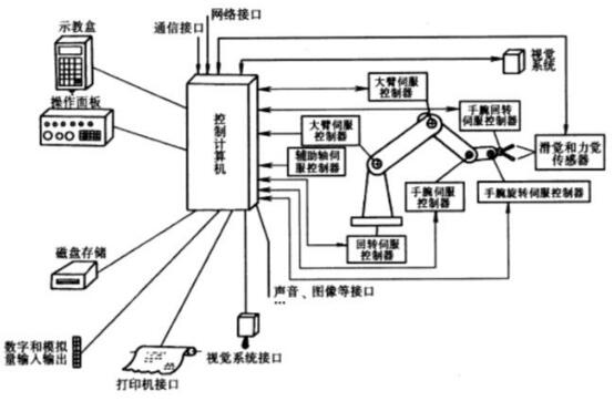
The design of the mobile robot motion control system mainly includes the function and architecture design of the system. The functional design mainly completes the software design of the control function and the algorithm, and the architecture design is the realization of the function on the hardware. According to different tasks and environments, the design of the mobile robot motion control system is also different. At present, the main problems in the robot motion control system are: the system is limited to a dedicated microprocessor, a special robot language, and the openness is poor; the software structure depends on the hardware of the microprocessor and it is difficult to transplant between different systems; the scalability is poor. To address these deficiencies, the following requirements should be considered when designing a robot motion control system:
(1) Open system architecture. Using open software and hardware architectures, it is possible to easily expand functions as needed to make it suitable for different purposes of scientific research needs;
(2) A reasonable modular design. Hardware modular design based on system requirements and electrical characteristics, not only to facilitate the installation and maintenance, but also to improve the reliability of the system; software is divided into different modules according to function, easy to modify, add;
(3) Real-time and multi-task requirements. The controller must be able to complete the processing of external interrupts within a defined time and can perform multiple tasks simultaneously;
(4) Network communication function to facilitate resource sharing and multi-robot coordination;
(5) It has certain intelligence and can judge and make decisions based on the actual situation, such as the processing when the given speed changes abruptly or outside the reasonable range, and the automatic diagnosis of the fault.
1, the robot's drive system
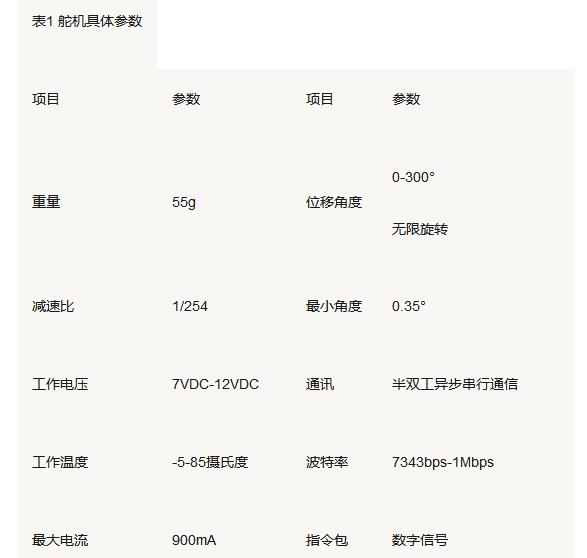
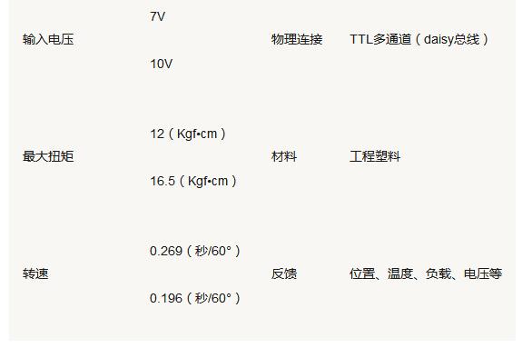
At present, DC motors, stepper motors and servos are more common in robot motion control. For my subject, a motor that can control the speed used as a Mcnam wheel also requires a motor that can precisely control the angle and can be used as a leg joint. After my preliminary estimation, the motor speed is not very large. If a DC motor is used, the speed reducer and the torque must be used to configure the speed reducer, and the angle cannot be controlled. If you use a stepper motor, you need to configure the driver. In order to meet the system's control requirements, considering the economy, etc., I'm going to use the Dynamixel series AX-12 steering gear which is a robot-specific servo motor. It can not only accurately control the angle, as a joint angle control, but also can be set as an infinite rotation mode through the software and used as a wheel.
The servo is a position servo driver for those control systems that require constant changes in angle and can be maintained. Its working principle is: The control signal enters the signal modulation chip from the channel of the receiver, and obtains the DC bias voltage. It has a reference circuit internally, which generates a reference signal with a period of 20mS and a width of 1.5ms, and compares the obtained DC bias voltage with the voltage of the potentiometer to obtain a voltage difference output. Finally, the positive and negative voltage difference is output to the motor driver chip to determine the positive and negative motor rotation. The AX-12 servo is an intelligent, modular power unit consisting of a microprocessor, an accurate DC motor, a gear reducer, a position sensor, a temperature sensor, and a control chip with communication functions.
Because AX-12 is equipped with an ATmega8 microprocessor inside, it is used to receive the data packet sent by the controller, and then the PWM signal is sent to the servo motor to control the start and stop of the motor through corresponding processing. Therefore, controlling the steering gear to actually control the state and parameters of the ATmega8 servo is stored in the corresponding addresses of the RAM and EEPROM of the ATmega8. The control of the servo is the process of reading and writing data to the corresponding address of the servo. Table 1 shows the specific parameters of the servo.
2, the robot's perception system
Environmental awareness is the most basic capability of a mobile robot except for moving. The level of perception directly determines the intelligence of the robot. The perception capability of the fU is determined by the perception system, which is an important I/O tool for robots interacting with the environment and humans, and is a window for robots to obtain information. The reason why mobile robots can target autonomous movement in a known or unknown environment and complete a certain job function is because it can sense external environmental information and its own status through multiple sensors.
The mobile robot's sensors can be divided into internal and external sensors. Internal sensors are used to detect the state of the robot itself. These are the sensors necessary to complete the movement of the robot, such as position and velocity sensors. They are one of the essential elements that make up the robot. Sensors used by external sensors to detect the environment and conditions of the robot depend on the tasks the robot is to perform, such as vision sensors, ultrasonic sensors, infrared sensors, and sound sensors. The robot uses these sensors to collect various kinds of information, and then adopts appropriate methods to comprehensively process the environmental information obtained by multiple sensors to control the robot to perform intelligent operations.
In addition to the internal sensors such as position, speed, temperature, supply voltage, and torque that are included in the AX-12 servo, the AX-S1 sensor module is also used as an external sensor in this design.
3, internal sensors
The AX-12 servo not only has a built-in position and speed sensor for detecting the rotation speed of the motor and the angle of rotation of the servo, but also sensors such as internal temperature, supply voltage and torque for detecting the internal state of the servo. When the AX-12 servo internal temperature, torque, power supply voltage, etc. exceed the rated range, it actively feedback this situation. In addition, it will flash the LED light or turn off the servo torque to protect itself.
4, external sensors
Dynamixel series AX-12 sensor module can be said to be "small, full-fledged sparrow", it includes infrared distance sensor, infrared remote control, sound detection sensor, photometric detection sensor, temperature detection sensor and also has the function of the buzzer .
Third, the robot control system design
The force condition during the robot movement may change constantly according to the road conditions, so the load of the motor is also constantly changing, so to achieve accurate control of the actuator (leg) stroke can not simply rely on the motor running time To qualify, it is necessary to install a sensor at the feedback position on the actuator so that when the actuator moves to a specified position, a feedback signal can be given to the motor through the control system to control the motor.
The six legs in 1, 3, 5, 2, 4, 6 are the same, so when the control design, only 1,2 legs with the example can be explained, 3,5 legs and 1 leg, 4 , 6 legs and 2 legs are the same.
(1) Sensor for the first leg:
Install the limit switch up and down in the limit position, upper limit B1, lower limit A1. Install the limit switch at the limit position and midpoint position of the forward/backward swing, front limit Z1, rear limit X1, and midpoint position O1.
(2) The second leg sensor:
Install the limit switch up and down in the limit position, upper limit B2, lower limit A2. Install the limit switch, front limit Z2, rear limit X2, midpoint position O2 at the extreme position and midpoint of the forward and backward swing.
Fourth, the conclusion
In the selection of the mobile mode, I first chose the McNam wheel, because the Mcnam wheel process is already mature and can move in all directions. Then the principle was elaborated. Followed by the design of the structure of the robot. First design the important leg structure, then the main part, this process is all done using UG7.5. After selecting the motor type, the servo was chosen because of its excellent function. In the design of the control system, the framework of the control system was simply designed in the end, and internal instructions and the like were not edited.
Smart Uv Printer,3D Photo Printer,3D Emboss Back Skin Printer,3D Relief Back Film Printer
Shenzhen TUOLI Electronic Technology Co., Ltd. , https://www.hydrogelprotector.com