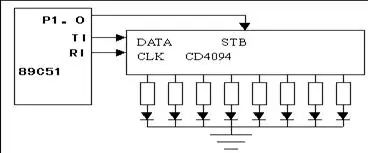
<Microcontroller serial port communication program design hardware connection diagram>
Example: Use the 8051 single-chip serial port to connect the CD4094 to expand the 8-bit parallel output port. As shown in the figure, each of the 8-bit parallel ports is connected to an LED, and the LED is required to be in a running light state. The serial port mode 0 data transmission can be interrupted or queried. In either case, the TI or RI flag should be used. When serial transmission, TI can be set (after sending a frame of data) to cause an interrupt request, send the next frame data in the interrupt service routine, or by querying the state of TI, as long as TI is 0, continue to query, TI is 1 End the query and send the next frame of data. At the time of serial reception, an interrupt is caused by the RI or an RI inquiry is made to determine when to receive the next frame of data. Regardless of the method used, the control register SCON must be initialized before starting communication. In mode 0, 00H will be sent to SCON.
-----------------Single-chip serial port communication program design column ------------------------- -
ORG 2000H
START: MOV SCON, #00H ; Set the serial port working mode 0
MOV A, #80H; the highest position light is on first
CLR P1.0 ; Turn off parallel output (the "dark red" phenomenon of each LED during the image transmission process)
OUT0: MOV SBUF, A ; start serial output
OUT1: JNB TI, OUT1; output is not finished
CLR TI; Finished, clear the TI logo for the next transmission
SETB P1.0; open parallel port output
ACALL DELAY; delay for a while
RR A ; loop right shift
CLR P1.0; turn off parallel output
JMP OUT0 ; loop
Note: The DELAY delay subroutine can use the delay subroutine used when we talk about the P1 port flow lamp. It is not given here.
Second, serial port asynchronous communication
Org 0000H
AJMP START
ORG 30H
START:
Mov SP, #5fh ;
Mov TMOD, #20h ;T1: working mode 2
Mov PCON, #80h ;SMOD=1
Mov TH1, #0FDH ; Initialize baud rate (see table)
Mov SCON, #50h ;Standard UART settings
MOV R0, #0AAH; the number to be sent
SETB REN; allowed to receive
SETB TR1; T1 starts working
WAIT:
MOV A, R0
CPL A
MOV R0, A
MOV SBUF, A
LCALL DELAY
JBC TI, WAIT1; if TI is equal to 1, clear TI and turn WAIT1
AJMP WAIT
WAIT1: JBC RI, READ; if RI is equal to 1, clear RI and turn READ
AJMP WAIT1
READ:
MOV A, SBUF; the number to be obtained is sent to the P1 port
MOV P1, A
LJMP WAIT
DELAY: ; delay subroutine
MOV R7, #0ffH
DJNZ R7, $
RET
END
Compile the program, write to the chip, insert the experiment board, and connect the experiment board to the serial port of the host computer with a read-through cable to experiment. The above program function is very simple, that is, to send the number 55H and AAH to the host at intervals, and send the number sent by the host to the P1 port. You can use the serial port wizard to do experiments on the PC side. The serial port wizard is available for download on my homepage. After running the serial port wizard, press the “Set Parameters†button on the main interface to enter the “Set Parameters†dialog box, and set the parameters as follows. Note that the serial port is used on my machine.
2. If you are not serial port 2, please change the serial port settings yourself.
After setting, press OK to return to the main interface. Note that there is a drop-down list on the right, and you should select “By hexâ€. Then press "Start to send", "Start receiving" will be fine. According to this setting, there should be two lights on the experiment board and 6 lights off. You can change the sending characters in the setting parameters such as 55, 00, FF, etc., observe the light on and off, and analyze the reason. You can also change the "by hex" in the drop-down list on the main interface. Observe the phenomenon in hexadecimal or "by ASCII characters" and analyze it carefully. This is also very good for everyone to understand hexadecimal, decimal, ASCII characters. The program itself is very simple and has comments, which are not explained here.
Third, the interrupt version of the above program
Org 0000H
AJMP START
Org 0023h
AJMP SERIAL ;
ORG 30H
START:
Mov SP, #5fh ;
Mov TMOD, #20h ;T1: working mode 2
Mov PCON, #80h ;SMOD=1
Mov TH1, #0FDH ; Initialize baud rate (see table)
Mov SCON, #50h ;Standard UART settings
MOV R0, #0AAH; the number to be sent
SETB REN; allowed to receive
SETB TR1; T1 starts working
SETB EA; open total interruption
SETB ES; open serial port interrupt
SJMP $
SERIAL:
MOV A, SBUF
MOV P1, A
CLR RI
RETI
END
Wall Ap Wireless Ap,Wall Mount Access Point,Wall Mount Wifi Access Point,Access Point Ac In-Wall
Shenzhen MovingComm Technology Co., Ltd. , https://www.movingcommiot.com