In the current reference design of the 3-5W LED-MR16 lamp, three 1W LEDs are used in series, and the input voltage is AC 12V±10%. If the LED drive circuit architecture adopts DC buck mode, it can output effectively under normal power supply conditions, but due to the stability of the electronic transformer, the input voltage of the LED drive circuit may be higher or lower than the output voltage, resulting in DC buck. The drive circuit does not work, and the LED current cannot be continuously turned on, which is the main cause of the LED-MR16 lamp flickering.
solution:
• The circuit architecture uses a buck-boost converter
• Wide drive voltage range and input protection
In order to solve the above-mentioned flicker problem, the LED driver circuit architecture uses a buck-boost converter as a better choice. The LED series circuit can be driven with an input voltage higher or lower than the output voltage. The buck-boost conversion circuit can achieve an efficiency of more than 85%, and suppress the change of the input voltage in the discontinuous operation mode to provide excellent line voltage regulation.
The new RT8450 can be specifically designed for driving applications in MR16LED lamps. Its internal circuit design architecture makes it easy to implement a buck-boost circuit, as shown in Figure 1.

Figure 1: The drive circuit for the LED-MR16 lamp is implemented using the RT8450 buck-boost architecture.
In addition, the RT8450 is available in a very small WDFN package with an input voltage range of 4.5-40V, which allows the RT8450 driver circuit to provide a wide drive voltage range and input protection. With an operating temperature of up to 125 ° C, the RT8450 can operate safely in high temperature environments within MR16 luminaires. Its 500kHz switching frequency allows the driver circuit to use small inductors and capacitors. In addition, the buck-boost circuit architecture can reduce the input filter capacitor capacitance, so that the driver circuit can be placed in the MR16 luminaire, as shown in Figure 2.

Figure 2: Driver board based on 5WMR16LED lamp and RT8450
Actually, the above application circuit is combined with the common electronic transformer on the market. The RT8450 does not flicker under any load conditions. As shown in Figure 3, the input voltage varies greatly due to poor load conditions of the electronic transformer. RT8450 down circuit using the LED-MR16 lamps, which LED remains constant current characteristic, flicker will not occur. The RT8450 switching frequency is approximately 500kHz, and the buck-boost circuit can use an input 68uF capacitor. The total converter efficiency (LED power divided by the power from VBAT) in this example can be as high as 85%. The RT8450 uses peak current sensing and average current control mode to ensure 5% LED current accuracy.

Figure 3: Channel 1 is the AC output voltage of the electronic transformer, channel 2 is the rectified and filtered input voltage, channel 3 is the AC input voltage, and channel 4 is the LED output current.
In addition, the RT8450 buck-boost architecture is characterized by the fact that the LED driver circuit is not affected by input voltage variations, and can support the pre-stage circuit to implement a triac TRIAC dimming scheme because this chip can utilize the TRIAC cutoff. After switching to the PWM signal, the RT8450 linear brightness adjustment pin can be controlled to control the brightness and brightness of the overall lighting scheme without flickering.
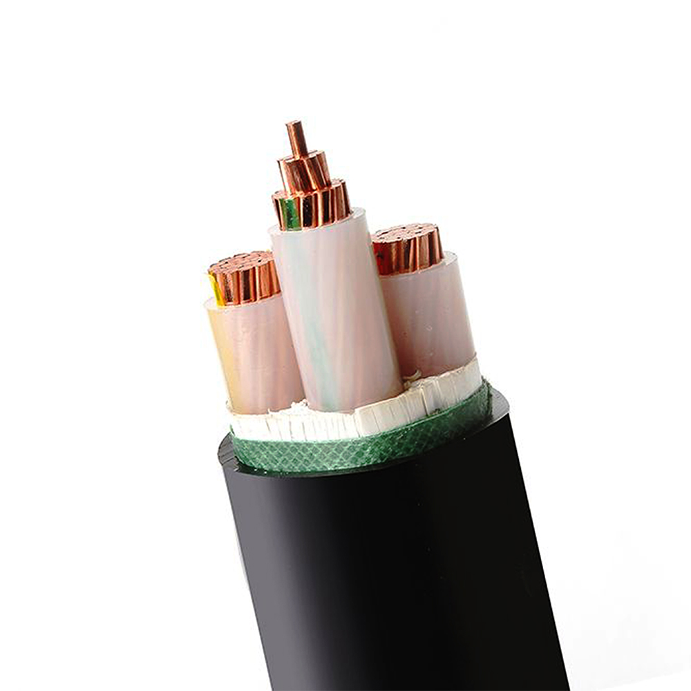
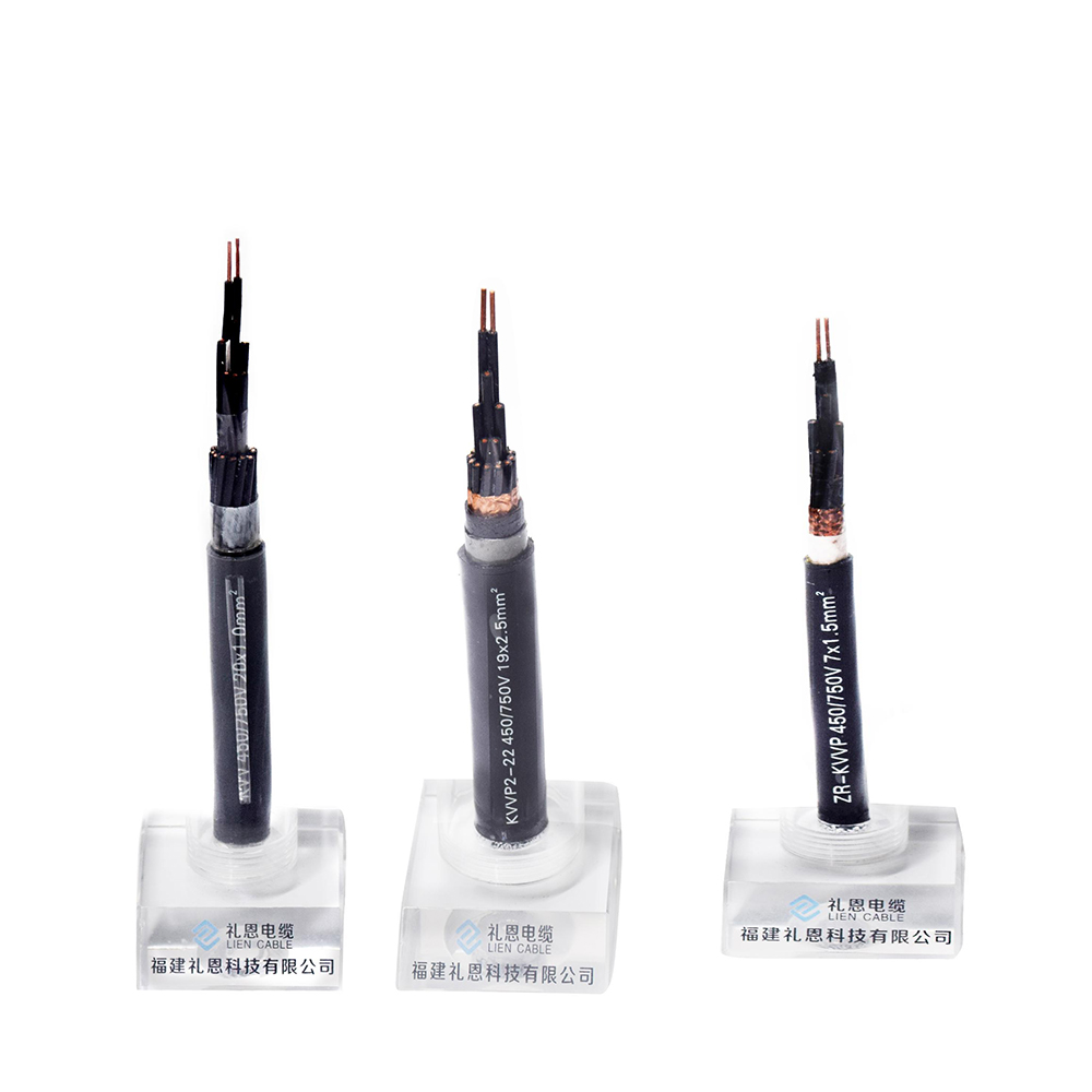
Control cable, insulated by PVC,XLPO/XLPE or PTFE material, is applicable for controlling and protecting circuits of rated voltage up to and including 450/750 V, used in enterprises of industrial and mining and department of energy source and transportation. It belongs to electrical equipments use cable which transmits electrical power from power system to various electrical equipments and tools.
Product specification
l Conductor type: stranded 99.95% OFC(oxygen free copper)
l Material :environmental friendly, fire resistant, flame retardant, low smoke halogen free, heat resistant
l Control cable color: black or other customized color
l Packing: carton packing, pallet packing, wooden steel drum or other packing method as requirements.
Three Main Type of our Control Cable
l PVC Insulated sheathed control cable
l Fire resistant control cable(PTFE)
l Radiation XLPO insulated control cable


Using features
*Rated power-frequency rated voltage U0/U is 450/750V
*Max. permissible continuous operating temperature of conductor:
l PVC Insulation type: 0℃
l XLPE Insulation type: 90℃
l PTFE Insulation type: 40℃~200℃
l XLPO Insulation type: 125℃
*The ambient temperature under installation should not be lower than 0℃, if the ambient temperature is below 0℃,the cable should be preheated.
Standard
This cable is manufactured according to GB/T9330-2008 standard. It can also be manufactured according to other standards upon request.
Application
Industrial and mining enterprises: iron and steel, coal manufacturing, etc
Modern high-rise building
Connecting line of electrical instruments and automation devices
For laying indoors, in trenches and in ducts, the cable should be shielded and for fixed installation.
Notes for installation
1. Don`t directly expose to the sunlight or superheat.
2. Don`t forget to check dry and wet level for installations in trenches regularly.
We can manufacture control cables as customer`s requirements. Welcome to contact us for more details about products and price. If later you want to visit our factory to get close to our production line, please also feel free to get in touch with us.
Control Cable
Control Cable,PVC Control Cable,Multicore Control Cable,Throttle Control Cable
Fujian Lien Technology Co.,Ltd , http://www.liencable.com