Using the principle of the oscillator, the DC power is first changed to a pulsed alternating current of a size that changes with time. The DC component is removed by the blocking system, the alternating component is retained, and then the transformation system (step-up or step-down) is used to transform, shape and regulate the voltage. We got AC power that meets our needs. An oscillating circuit is used to generate a pulsating DC current of a certain frequency, and this transformer is then used to convert this current to a desired AC voltage. Three-phase inverters generate three-phase AC voltages that differ in phase angle by 120 degrees at the same time.
There are many parts of the inverter, the most central part of which is the oscillator. The earliest oscillators were of the electromagnetic type, and later they were developed into electronic types. From discrete components to dedicated integrated circuits to micro-computer control, they became more and more perfect, and the functions of the inverter became stronger and stronger. A very wide range of applications.
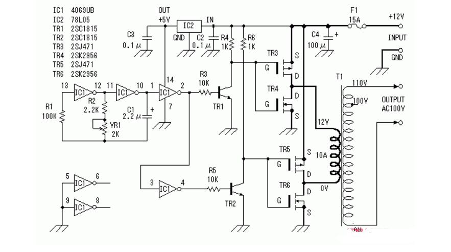
Simple DC to AC inverter circuitThe inverter uses a power field effect transistor as an inverter device. Use car battery power. Therefore, the input voltage is 12 volts DC. The output voltage is 100V AC. However, the input and output voltages are not limited to this. You can use any voltage. They rely on transformers. Waveform output is square wave. According to experience, this circuit is about 100W power.
The circuit must be fused as the oscillator stops when too much input current flows.
It is relatively simple to convert 220V AC to 24V, 36V, and 48V, using only the transformer principle. Electromagnetic mutual inductance, you can get different voltages.
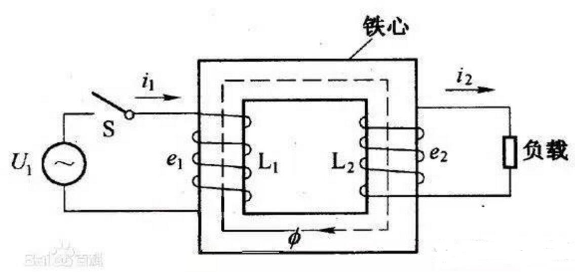
Assume that the closed circuit is a n-turn coil, and the change rate of the magnetic flux passing through each coil is the same. This is equivalent to n single-turn coils connected in series, so the induced electromotive force becomes

According to the formula, E is the electromotive force, which is the voltage. because  No change, as long as the number of coils at both ends of the iron block is different, the effect of voltage change can be achieved.
Converting alternating current to direct current can achieve the desired effect simply by adding a diode. A diode is a device with two electrodes that allows only current to flow in a single direction. Many applications use its rectification function. Then use the transformer principle to convert 220V AC into 12V DC, and the 5V DC output voltage of our mobile phone charger.
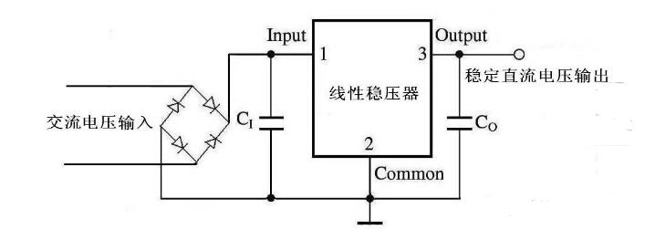
So how to convert 12V DC to 220V AC? First of all, let's look at the inverter, what is the inverter?
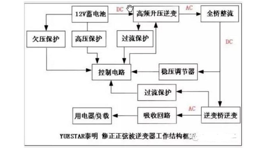
Inverters convert DC energy (batteries, storage batteries) into AC (typically 220V, 50Hz sine wave). It consists of an inverter bridge, control logic, and filter circuits. It is a DC to AC transformer. In fact, it is a voltage inversion process. The converter converts the AC voltage of the power grid into a stable 12V DC output, and the inverter converts the 12V DC voltage output by the Adapter to high-frequency, high-voltage AC power.
Then we look at the circuit diagram of the entire process: 12V DC → high frequency boost → 220V DC → full bridge rectifier → 220V DC → inverter bridge → 220V AC
High-frequency step-up inverter control circuit:
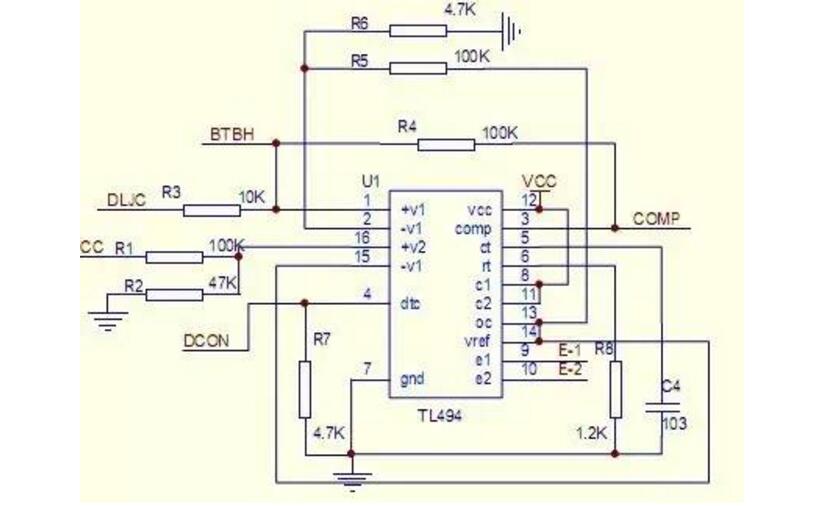
(1) The non-inverting input of the first set of amplifiers of the feet detects the output current and divides the voltage with the three 0.33R resistors. When the current is too high, the voltage across the divider resistor exceeds the (2)-pin reference voltage, and (3) the foot The output of the amplifier output is high, and when the (3) pin is high, the circuit enters the protection state. (2) The pin is the inverting input of the comparator. It is connected to the reference of (14) pin and used as the reference voltage of the comparator. The control signal of the external input can be input to the control end of the cutoff time of the pin (4) (also called the dead time Control), and the input terminals of the error amplifier of the feet (1), (2), (15), and (16), the offset voltage of the input terminal is 120mV, which can limit the output cutoff time to the minimum value, which is about the initial sawtooth wave 4% of cycle time. When the 13-pin output mode control terminal is grounded, a maximum duty cycle of 96% can be obtained, and when the (13) pin is connected to the reference voltage, a 48% maximum duty cycle can be obtained. If we set a fixed voltage at the 4th leg off time control input, and its range is from 0V to 3.3V, the additional cutoff time must appear on the output. (5) and (6) The foot is a fixed-frequency pulse width modulation circuit. A linear sawtooth oscillator is built in. The oscillation frequency can be adjusted by an external resistor and a capacitor. The oscillation frequency is as follows:
The width of the output pulse is achieved by comparing the positive sawtooth voltage on the capacitor CT with the other two control signals. Power output tubes Q1 and Q2 are controlled by a NOR gate. When the clock signal of the flip-flop is low, it will be gated, that is, it will be gated only when the sawtooth voltage is greater than the control signal. As the control signal increases, the width of the output pulse will decrease. (7) Foot ground, (8), (11) The foot is the collector of the switch of Q1 and Q2. Connect the power supply in this circuit. (9) and (10) are the emitters of Q1 and Q2. The switch driver output is connected to the Q1 and Q2 external amplifiers in the figure below. To drive the rear pole push-pull circuit. (12) Pin power supply, (13) pin is the output control terminal. When the (14) pin reference voltage is connected, the two output pulses are 180 degrees out of phase with each output being about 200MA to drive a push-pull or half-bridge circuit. (15). The inverting input of the second group of amplifiers is connected to the reference voltage, and the (16) non-inverting input is used to detect the supply voltage. When the voltage is too high to exceed the (15) foot reference voltage, (3) pin output high, the circuit enters the protection state.
High frequency boost inverter circuit and rectification:
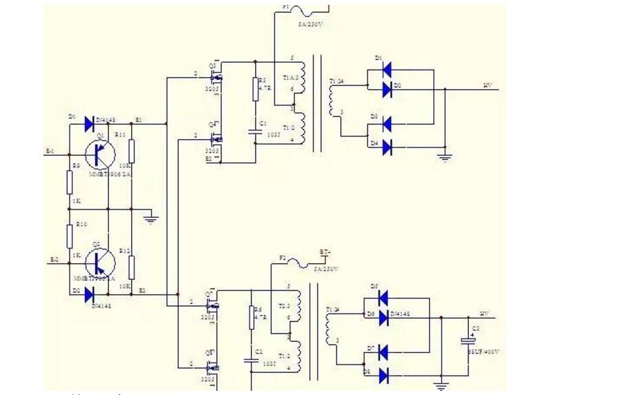
This is a push-pull topology inverter circuit, when the E1 drive pulse drive, Q1 conduction, so that VT3, VT6 conduction, VT7, VT8 cut off, this time the circuit performs a positive half-waveform amplification, the transformer boosted to the secondary, Rectified by high-frequency rectifier tube, when E2 pulse drive, Q2 conduction, driving VT7, VT8 conduction. VT3, VT6 cut-off, enter the negative half cycle waveform amplification. After step-up transformer boost, high-frequency rectifier.
(This VT3\6\7\8 exists in the circuit in a push-pull manner. Each is responsible for the waveform amplification task of positive and negative half cycles. When the circuit is working, only two pairs of symmetrical power switch tubes are turned on at a time, so the conduction Low loss and high efficiency. Push-pull output can both sink current to the load.)
Inversion bridge inverter:
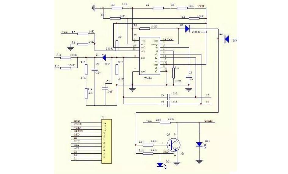
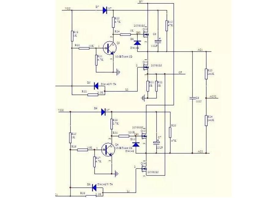
Finally, the pin 5 of the TL494CN chip is connected to the external capacitor C3 and the pin 6 of the external resistor R15 determines the pulse width frequency to be F=1.1÷(0.1&TImes;220)KHZ=50HZ. The control Q10, Q11, Q13, and Q14 work at a frequency of 50Hz. Invert 220V DC into 220V/50Hz alternating current. The above figure will complete this part of the function. In the forward direction of TL494, IC2 controls Q3 to be in saturation conduction state and Q4 is in the OFF state. Since Q3 is in the saturation conduction state, Q10 is the saturation conduction state. Since Q4 is in the off state, Q11 is in an off state because there is no positive bias on the gate, and Q14 is in an off state because there is no positive bias on the gate, and Q13 is a saturated conduction state. At this point, 220V DC is passed through VT6 along the XAC socket to the load and then grounded through VT10 to form a positive half-cycle current. In the reverse direction, IC2 controls Q3 to be off and Q4 is a saturated conduction state. Since Q3 is off, Q10 and Q13 Since the gate is in the off state without positive bias, Q11 is in a saturated conduction state, Q11 is in a saturated conduction state, and Q14 is in a saturated conduction state, and Q11 is in an off state because the gate has no positive bias. At this point, 220V DC power is sent through the VT9 along the XAC socket to the load and then grounded through the VT7 to form a negative half-cycle current; this connects the 220V DC power to a 220V/50HZ AC output for load use.
Circuit protection circuit:
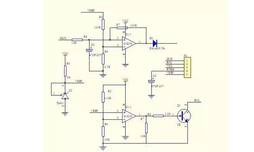
The circuit adopts the dual opamp comparator amplifier LM358 to control the output over-current protection, and the output voltage is too low to protect the circuit. The TL431 sets a 2.5V reference voltage here, and provides a reference voltage to the comparator non-inverting input. The first group of op amps is in phase. The input termination is connected to the output current detection and the inverting input is terminated to the reference voltage. When the current is too high, the input voltage of the comparator rises. When the voltage exceeds 2.5V, the output terminal outputs a high level, which is sent to pin 3 of the IC1 and the IC turns off the output. . The second set of operational amplifiers is connected to the non-inverting input with a reference voltage and the inverting input is terminated with an output voltage. When the voltage is too low, the output voltage is lower than 2.5V after the partial voltage is detected, the output terminal outputs a high level, Q1 is turned on, and the buzzer is turned on. Call the police.
ZGAR Aurora 2500 Puffs
ZGAR electronic cigarette uses high-tech R&D, food grade disposable pod device and high-quality raw material. All package designs are Original IP. Our designer team is from Hong Kong. We have very high requirements for product quality, flavors taste and packaging design. The E-liquid is imported, materials are food grade, and assembly plant is medical-grade dust-free workshops.
Our products include disposable e-cigarettes, rechargeable e-cigarettes, rechargreable disposable vape pen, and various of flavors of cigarette cartridges. From 600puffs to 5000puffs, ZGAR bar Disposable offer high-tech R&D, E-cigarette improves battery capacity, We offer various of flavors and support customization. And printing designs can be customized. We have our own professional team and competitive quotations for any OEM or ODM works.
We supply OEM rechargeable disposable vape pen,OEM disposable electronic cigarette,ODM disposable vape pen,ODM disposable electronic cigarette,OEM/ODM vape pen e-cigarette,OEM/ODM atomizer device.

Aurora 2500 Puffs,ZGAR Aurora 2500 Puffs Pod System Vape,ZGAR Aurora 2500 Puffs Pos Systems Touch Screen,ZGAR Aurora 2500 Puffs Disposable Vape Pod System,2500Puffs Pod Vape System
Zgar International (M) SDN BHD , https://www.zgarvapepen.com