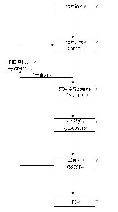
Hardware design block diagram:

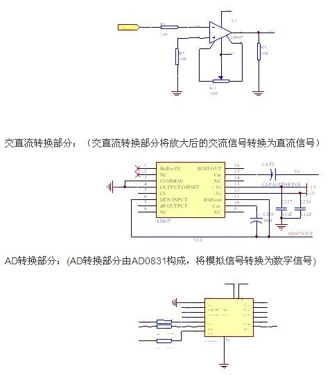
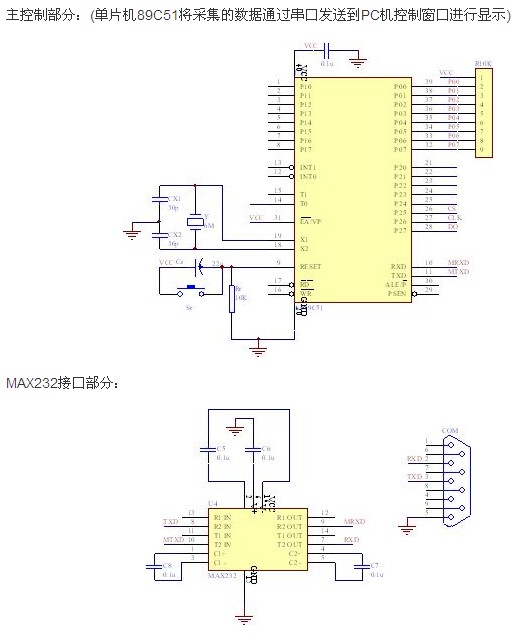
It can be seen from the schematic diagram that the measured periodic AC signal is first amplified by the op amp OP07, and the amplified signal is converted into a DC signal by the AC-DC converter AD637, then AD conversion is performed by the ADC0831, and the converted digital signal is transmitted by the single-chip microcomputer. The acquisition is performed, and the last sampled data is output to the PC through the serial port for display. According to the voltage range of the input signal, it needs to be separately amplified. This part mainly relies on the multi-way switch CD4051 which is programmed by the single-chip microcomputer.
Description of each main circuit
Signal amplification part: (Signal amplification part consists of op amp OP07 and multi-channel analog switch CD4051)


Commissioning results and error analysis
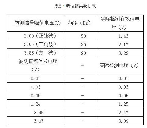
According to the above scheme, the detection circuit is debugged, and the input weak signal may be a sine wave, a triangle wave or a square wave, and the voltage range thereof is 10 μV to 5 V, and the frequency range is 10 Hz to 1 MHz. The debug data is shown in Table 5.1 below:

Analysis of debugging results: First, the main cause of error is that the input signal source will generate a small amount of ripple, and the accuracy of the OP07 itself will also affect the test results. Second, the voltage range of the input signal cannot exceed 4.16V. It is determined by the AD conversion chip itself selected.
High Frequency Inverter,High Frequency Power Inverter,high frequency pure sine wave inverter ,high frequency sine wave inverter
SUZHOU DEVELPOWER ENERGY EQUIPMENT CO.,LTD , https://www.fisoph-power.com