In "embedded programming of the basic structure of the microcontroller, working principle" , "embedded peripheral circuit of embedded programming microcontroller" and "single-chip programming language and development environment" , we learned the hardware and programming language of the microcontroller and the development environment Wait. This article will take you through the basics of peripheral circuit control of the microcontroller.
(SFR) Special FuncTIon Registers
The MCU has the same function as the box. We call it a register to temporarily store data. The types of registers include program counters, general-purpose registers, and SFRs (Special Function Registers).
SFR is mainly used to set the working mode of peripheral function circuits (counter or serial port, general-purpose I/O, etc.), confirm its working status, and control it. In other words, SFR is not just a "box" for saving data. By changing the data stored in the "box", not only can the peripheral function circuit be changed, but the data in the "box" will also change with the working state of the peripheral function circuit.
Basic knowledge of controlling peripheral function circuits
The following takes general-purpose I/O as an example to illustrate the control of the peripheral function circuit of the single-chip microcomputer. General purpose I/O has the following features:
Output function: can output high level voltage or low level voltage
Input function: can read the voltage level input to the pin
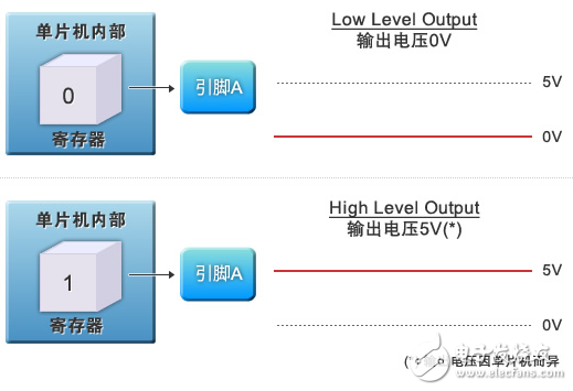
First look at the control of the output function. Pin A in Figure 1 is a general purpose I/O.
If register to pin A (SFR)
Writing a 0 will cause the output voltage of pin A to be low (0V).
Writing a 1 will cause the output voltage of pin A to be high (5V).

Figure 1: Output function of general purpose I/O
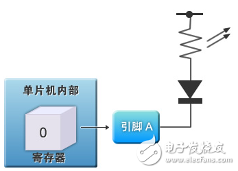
If pin A of Figure 1 is connected to an LED, a circuit that controls the LED can be constructed (see Figure 2). At this time, when 0 is written to the register (SFR), the LED is turned on, and when 1 is input, the LED is turned off. Although this is a very simple action, it reflects the basic principle of the microcontroller to control various peripheral functional circuits. With this function, it is possible to perform the same switching function as the ON/OFF of the motor (since the normal current cannot be passed through the driving circuit of the single-chip microcomputer, a motor driving circuit made of a FET or a transistor must be separately prepared). In addition, more complex controls can be accomplished if multiple general purpose I/O ports are used.

Figure 2: LED control circuit for general purpose I/O
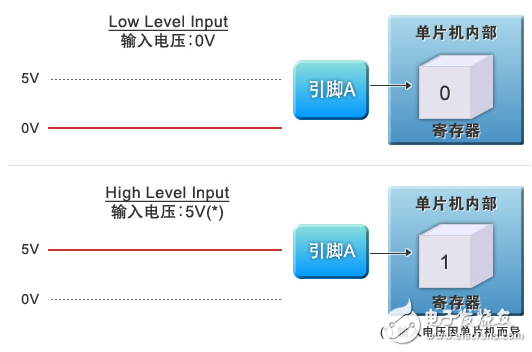
Next, look at the input function (Figure 3).
If a low level voltage (0V) is input to pin A, 0 is read from the register (SFR).
If a high level voltage (5V) is input to pin A, a 1 is read from the register (SFR).
That is, by reading the value of the register (SFR), it can be judged whether the external voltage is a low level voltage or a high level voltage.

Figure 3: Input function of general purpose I/O
The products can provide various specifications of rectifier bridge devices according to customer requirements. The electrical properties, appearance, reliability, safety indicators and environmental protection indicators of the products all meet the relevant standards.
Planar Die Construction Sealed Glass Case Ideally Suited for Automated Insertion - 75V Nominal Zener Voltages
Case: MiniMELF, Glass Terminals: Solderable per MIL-STD-202, Method 208 Polarity: Cathode Band Approx. Weight: 0.05 grams= 25°C unless otherwise specified Symbol Pd VF RqJA Tj, TSTG Value to +175 Unit mW V K/W °C
Characteristic Forward Voltage = 200mA Thermal Resistance, Junction to Ambient Air (Note 2) Operating and Storage Temperature Range Notes:
1. Tested with Pulses, 20ms. 2. Valid provided that Electrodes are kept at Ambient Temperature.
1. Tested with pulses = 20 ms. 2. Valid provided that electrodes are kept at ambient temperature.
VZ, ZENER VOLTAGE (V) Fig. 1, Zener Current vs Zener Voltage
25 20 VZ, ZENER VOLTAGE (V) Fig. 8, Zener Current vs Zener Voltage
TA, AMBIENT TEMPERATURE (°C) Fig. 3, Power Dissipation vs Ambient Temperature
15 20 VZ, ZENER VOLTAGE (V) Fig. 4, Differential Zener Impedance
VZ, ZENER VOLTAGE (V) Fig. 5, Junction Capacitance vs Zener Voltage
MINI MELF,Smd mini melf,zener mini melf,mini melf package,mini melf resistor,mini melf diode,mini melf resistor datasheet
Changzhou Changyuan Electronic Co., Ltd. , https://www.changyuanelectronic.com