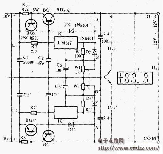
This article introduces a special DC stabilized power supply. It differs from other power supplies in that the continuous adjustable range is extremely wide. Simply turn a voltage regulator knob to achieve continuous and smooth output voltage between positive and negative. Change, and the stability is higher.
This new type of power supply is extremely versatile and can be used in special occasions such as DC motor stepless speed change and forward and reverse steering, gate turn-off thyristor GTO devices and bidirectional trigger devices.
The electrical principle of this special power supply is shown in Figure 1. The three-terminal adjustable voltage regulator integrated circuit lC and IC "constitute the power supply core. lC and its peripheral components constitute a positive output regulated power supply, IC" and its peripheral components constitute a negative output regulated power supply, the two constitute positive and negative interaction The main and auxiliary series superimposed power supply circuit. The main and auxiliary circuits are completely symmetrical and the component parameters are identical.
Linear coaxial double potentiometer Wl and W"l adjustable output voltage of positive and negative power supply. The connection form of Wl and W"l ensures that their resistance values ​​Rwi and Rw,1 always maintain a complementary relationship, ie Rwi+Rw , i=w, thus ensuring that the absolute values ​​of the output voltages of the positive and negative power supplies are always in a complementary relationship.
The relationship between the output voltage Uo and the voltages UAC and UCA at both ends of the capacitors C4 and C4' is as follows: when UAC>UCA", Uo>o; when UAC=UCA, Uo=0; when UAC 
The circuit shown in the above figure has an output voltage range of -12V to +12V and a load current of up to 3A.

The relationship between the resistance of the potentiometer and the output voltage Uo is shown in the figure above.
Dl, D2 protection diodes, under normal conditions are in a reverse bias state, does not work. When the input voltage suddenly drops due to any reason (such as C2 failure breakdown or open input), the output capacitor C4 will discharge through the IC's small current junction input terminal. At this time, Dl can effectively clamp the IC output and input terminals. The limit is around 0.7V, which protects the IC. When the output voltage suddenly drops (such as C4 failure breakdown or output short circuit), the circuit capacitor C3 of the regulation terminal is discharged, and D2 can protect the IC from damage.
Continuously adjustable regulated power supply operates under the harsh conditions of large input-output differential voltage. The three-terminal regulator integrated circuit is equipped with current limiting protection, power tube safety zone protection and chip overheat protection, even in ideal heat dissipation. Under the conditions. The LM317 can only load 1.5A current or 15W power capacity, which is far from meeting the design requirements of this power supply. To this end, an external high-power transistor BG1 is added to expand the output current of the LM317, reducing l. The power consumption of the M317 fully maintains the excellent performance of the lC. The expanded output current and power capacity are determined by the limit parameters ICM and PCM of BG1. However, after the external power transistor expansion method is adopted, the external device BG1 lacks protection. To this end, BG2 and R3 must be added to implement current limiting protection for BG1. The external expansion device BG1 must take reasonable heat dissipation measures.
1C can also choose 7800 series three-terminal fixed output voltage regulator integrated circuit, but the performance of linear adjustment rate, load regulation rate and ripple rejection ratio is slightly worse.
Function description
The socket is ordinary converter,with two output 5V2A power USB power supply at the same time,can be very convenient in use electrical appliances and recharge the equipment at the same time,such as digital products like Iphone Ipad,MP3,MP4 etc.The charge apply to full range of international AC output,no-load power consumption less than 0.3W,with short circuit,overload,over-voltage protection,can be convenient for your life and save more energy
Timer Control Time Adgustment
1.Press the power switch 1 time,the 1HOUR LED will light on.The Timer into ON mode,USB and control socket output ON .
2.Continuously press the power switch the LED light on,the Countdown mode and LED light on will cycle change from 1HR,2HR,4HR,6HR,8HR,10HR.
3.Choose you need countdown time mode,the mode LED will lighto on,start countdown until countdown time finish,the control output and USB change to OFF
4.Then the countdown is start,The Time indicate LED will from high to low auto change until Countdown finish off.
Failure analysis:
1.check whether the power supply connection is good
2.check whether the USB cable is loosen
Warning Note:
1.Use indoor and dry location ONLY
2.The load max does not exceed 15A 3600W
3.This product does not convert voltage please do not miss use DO NOT exceed the maximum loading of 3600 Watts 15A
4.Always have earth connection for safety reason
5.If in doubt please consult with a qualified electrician
USB charger socket, USB socket, USB plug, USB plug socket
NINGBO COWELL ELECTRONICS & TECHNOLOGY CO., LTD , https://www.cowellsocket.com