In recent years, with the continuous development of the automotive industry and the electronics industry, automotive wire-steering steering technology has become a research hotspot, and many key issues including road-sensing simulation, steering stability and bus technology have been proposed and studied. Among them, the bus technology has been actively researched and applied by many well-known automobile companies. Some automakers are currently planning to use the FlexRay bus, a network communication bus that is particularly well-suited for next-generation automotive applications, with fault-tolerant functionality and deterministic messaging times to meet the high-speed communication requirements of automotive control systems.
FlexRaY is a time-triggered communication bus that requires high real-time performance, so relying solely on embedded programs consisting of simple loop and interrupt service routines will not meet the requirements. At the same time, during the startup and operation of FlexRay communication, it is necessary to use the loop to query the bus status, which wastes a lot of system resources and is easy to cause program deadlock, which becomes a difficult problem in the application.
Based on the above problems, this paper designs the communication part of the FlexRay bus in the line-controlled steering based on the μC/OS-II operating system. On the basis of satisfying the real-time requirements, the multi-tasking features are used to save system resources, avoid the deadlock problem, and increase the communication fault detection and alarm function, which lays a foundation for the development of the line-controlled steering system in the future.
1 FlexRay bus technology In order to meet the needs of automotive wire control technology, the FlexRay Alliance released the FlexRay bus protocol in 2005. Its main features are: dual channel transmission, each channel transmission rate up to lO Mb / s; flexible use, support a variety of network topology; high load rate; provide redundancy mechanism.
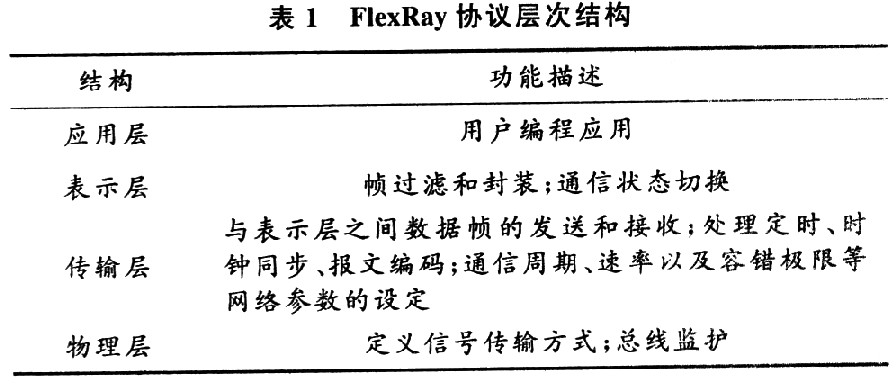
From the perspective of the open system interconnection reference model, the FlexRay communication protocol defines a four-layer structure: the physical layer, the transport layer, the presentation layer, and the application layer. The functional description of each layer is shown in Table 1. In the presentation layer, the communication state switching controls the operation of the entire FlexRay communication and plays an important role.

This article refers to the address: http://
The FlexRay protocol operation control (POC) divides the communication status into several states: configuration status (default configuration, configuration); ready status; awake status; startup status; normal status (normal active, normal passive) ; pause state. Its state transition diagram is shown in Figure 1. After the controller host interface (CHI) sends a command to the communication controller (CC), the CC enters the default configuration state from the suspended state, enters the configuration state after the configuration condition is met, and completes the network initialization and node communication task initialization; You can enter the ready state and complete the internal communication setting of the node. If the communication ready condition is not met, return to the configuration state to continue configuration; in the ready state, the CC can send a wake-up frame, wake up the node in the network that is not communicating, and can also start the CPU. The communication command completes synchronization with the FlexRay network clock; after the startup is successful, it enters the normal state and completes the data transmission and reception; when an error occurs, the pause state can be entered from the normal state, and the CHI command is re-waited.

It can be seen that the controller needs to perform corresponding operations according to the POC state, so loop detection of the POC state occurs, which is likely to cause program deadlock and occupy a large amount of system resources. According to the introduction of the operating system, the task is in the form of a loop, so the detection POC state can be performed separately in the task, and the task scheduling can be performed through the operating system, which can avoid affecting the running of the program in other tasks, and improve the program. Execution efficiency.
2 μC/OS-II transplantation based on MC9S12XF512 μC/OS-II is an operating system with open source code, featuring high execution efficiency, small footprint and excellent real-time performance. By using the operating mechanism's task mechanism and designing and implementing the Flex-Ray protocol, the real-time and stability of the system can be greatly improved, and the deadlock phenomenon when detecting the POC state can be avoided.
There are currently fewer microcontrollers supporting FlexRay communication on the market, and only Freescale's technology is relatively mature. Taking into account the cost problem, the 16-bit microcontroller MC9S12XF512 is selected as the system controller chip. The first thing to solve the use of the operating system is the migration problem. According to the file structure of μC/OS-II, it is necessary to migrate to OS_CPU. H, (OS_CPU_A.ASM and OS_CPUC.C three files are modified to suit the needs of the MC9S12xF512 chip.
2.1 Modify the OS_CPU. H file OS_CPU. The H file defines hardware information related to the CPU, including the storage length corresponding to various data types. The stack in MC9S12xF512 is increased from high address to low address, so the constant OS_STK_GROWTH must be set to 1. At the same time, the task scheduling function OS_TASK_SW() is defined as a soft interrupt source.
2.2 Modify OS_CPU_A. ASM file OS_CPU_A. The ASM file is code written in assembly language related to the task scheduling part. It includes a task-level task switching function OSCtxSw(), an interrupt-level task switching function OSIntCtxSw(), and a function OS-StartHighRdy() that causes the highest-priority ready-state task to start running.
The MC9S12XF512 chip not only has a FLASH page management register PPage, but also a RAM page management register RPage, an E2PROM page management register EPage, and a full-range register GPage. When a clock tick interrupt occurs, the chip automatically pushes the CPU registers onto the stack, but does not include the above registers, so it is in OS_CPU_A. In the three functions of the ASM file, you need to add the statement to stack and pop the registers. Due to limited space, only the PPage code is used as an example: 
The stack of registers must be in the order of GPage, EPage, RPage, PPage, and the stack is reversed.
2.3 Modify OS_CPUC. C file OS_CPUC. The C file is code written in the C language related to the task scheduling part, including the task stack initialization function OSTaskStklnit() and the clock tick interrupt service routine OSTicklSR().
2.3.1 Modify Task Stack Initialization Function 0STaskStkInit()
Since μC/OS-II uses the interrupt method to implement task scheduling, it is necessary to use the function OSTaskStklnit() to simulate the stack structure after an interrupt occurs, and reserve the register storage space according to the stacking order after the interrupt, and the interrupt is returned. The address points to the starting address of the task code. When writing, it is necessary to write the code according to the stacking order of the X, Y, A, B, SP and other registers after the chip is interrupted. First set a breakpoint at the routine OSTaskStkInit() function, and then step through the program to see if the register state of X, Y, A, B, SP, etc. corresponds to the stored value programmed. It is found that the storage area address corresponding to the stack pointer SP value is the storage address of the stack when the analog interrupt is generated, and the content of the task program pointer address is incorrect, that is, it is not the pointer address of the task, so each time the task execution needs to be called Both entered the wrong address for execution and did not find the code for the task. By stepping through the OSTaskStkI-nit() function, it can be found that when the original program stores the task code pointer PC value, only the upper 8 bits of the PC pointer are stored, but the last 8 bits are not stored, resulting in the pointer pointing to the error. So modify the program to:
*--wstk=(INTl6U)((INT32U)task);
2.3.2 Modify Clock Beat Interrupt Service Subroutine OSTickISR()
The clock tick interrupt service routine OSTickISR() is responsible for handling all timing related tasks such as task delays, wait operations, and so on. In the clock interrupt, the task in the waiting state will be queried to determine whether the delay is over, otherwise the task scheduling will be resumed. This can be done by calling OSIntEnter(). The OS_SAVE_SP(), OSTimeTick() and OSIntExit() functions are implemented. The OSintEnter() function notifies μC/OS-II to enter the interrupt service routine, the OS_SAVE_SP() function is used to save the stack pointer, and the OSTimeTick() function decrements the task delay counter that requires a delay of several clock ticks, when the program is repeatedly run. When the counter is 0, it indicates that the task has entered the ready state, and the OSintExit() function marks the end of the clock tick interrupt service subroutine.
The most important point after that is to add the interrupt service routine OSTickISR() and the task-level task switching function OSCtxSw() to the corresponding location in the system interrupt vector table. The real-time clock interrupt module (RTI) is used here to implement the clock interrupt, so OSTickISR() is connected to the vector table RTI position. The OSCtxSw() function uses a soft interrupt to implement the task switching function, so the vector address of the soft interrupt service routine must point to OSCtxSw().
After the above program is written, the code is downloaded to the hardware, and μC/OS-II can be run on the system.
3 Communication program design uses the task form to solve the problem of detecting POC status, which not only can improve the efficiency of the program and avoid the dead loop phenomenon. At the same time, it can also establish the communication fault detection alarm task to provide the driver with fault information under different communication states. Easy to handle.
The wire-steering program structure includes four parts: system initialization, communication control, data acquisition and control algorithms. Only the system initialization and communication control sections are designed here.
3.1 System Initialization In the main program main(), the MC9S12XF512 chip is initialized first, including: clock initialization, I/O port initialization, A/D module initialization, PWM module initialization, and FlexRay protocol configuration initialization. After that, the OSInit() function is called to initialize the μC/OS-II operating system. Then create three tasks, according to the priority order 9, 11, and 13, respectively, for the FlexRay communication start task, data receiving and sending task and fault detection alarm task, these three tasks realize the communication part function of the wire-controlled steering system, other parts Features can be extended by creating additional tasks. Finally, call OSStart() to start the kernel run and let the task run under the management and scheduling of the operating system.
3.2 Communication task design Based on the driver developed by Freescale for the FlexRay communication transport layer and presentation layer of the chip, the application layer programming is performed, that is, the communication task program is written to complete the running process of the protocol.
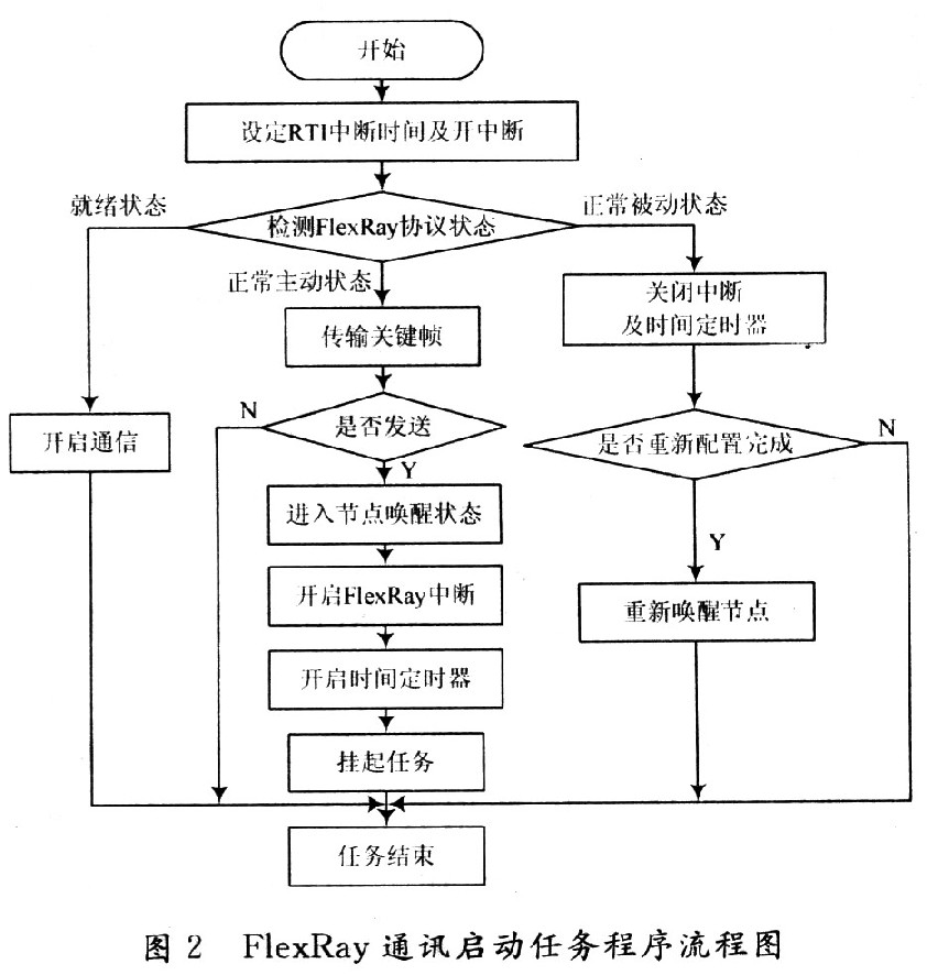
3.2.1 FlexRay communication startup task According to the protocol defined in the FlexRay protocol described above, when the FlexRay communication is initially configured, the protocol will enter the ready state, and then the start node command will be sent to wait for the protocol state to change from the startup state. In the normal active state, in the normal active state, the key frame is first sent to start other nodes in the network, after the completion of the transmission, the node wakes up, and then various interrupts of the FlexRay communication are started, including: transmission interruption, reception interruption, storage area Interrupts and timer interrupts, etc., and finally suspend the task to wake up when a communication failure is detected; the normal passive state of the protocol is to reconfigure the protocol and restart the protocol when the communication fails. It should be noted that the user must turn on the clock metronome after the multitasking system is started, that is, after calling Osatart(), the RTI interrupt is enabled by the task with the highest task priority, otherwise the system is easy to deadlock. The program flow chart is shown in Figure 2.

3.2.2 Data Receiving and Sending Tasks The receiving and transmitting of FlexRay data is performed by the interrupt service program. Therefore, in this task, it is only necessary to judge whether the POC state enters the normal active state, and if so, the global variable pair receiving function Fr_receive_da is used. And the message buffer of the send function Fr_transmit_data() performs data reading and updating.
3.2.3 Fault Detection Task During the communication process, when other nodes restart due to a fault or the communication line is interrupted, the fault detection task can be used to check the POC status. When the protocol runs in the normal passive state, it is determined that the communication line appears. Fault, the fault LED indicator is set to flashing state; when the protocol is running in the pause state, it is judged that the node controller is faulty, the fault LED indicator is set to be always on, and the FlexRay communication startup task is unmounted. Reconfigure the protocol. After the fault is resolved, the system can automatically start the node operation. The program flow chart is shown in Figure 3.

4 Experimental verification Using Vector's CANoe software, you can easily observe the data flow on the FlexRay bus. In the experiment, the FlexRay interface board VN3600 provided by CANoe software is connected to the bus network. After that, the MicroTick of FlexRay communication in the MC9S12XF512 chip manual is defined as 25 ns. Therefore, in the FlexRay initialization definition, the parameter P_MICRO_PER_M-ACRO_NOM is set to 40, then one. MareroTick is equal to 40 MicroTicks, which means that the reference time slice of the FlexRay communication configuration is 1μs. According to this, the configuration communication cycle is 5 000 μs; one static time slot length is 24 μs, a total of 91; one dynamic time slot is 5 μs, a total of 289; feature window and network idle time is 1 371 μs.
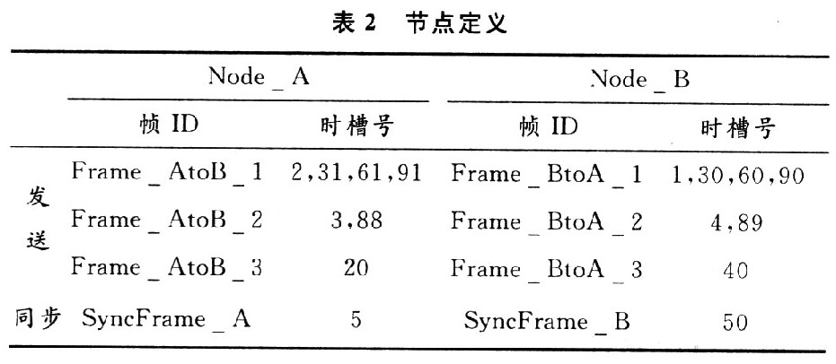
The time slot definitions for nodes Node_A and Node_B in the program are shown in Table 2.

The experimental results are shown in Figure 4. The running time is 2 289 s. The time slot change and the number of cycles are consistent with the design, and the data transmission and reception is normal. As can be seen from Fig. 5, the frame rate is 3 200 frames/s, and a total of 7 369 600 frames are transmitted. No invalid frames and error frames are present, which meets the requirements of real-time and stability.


In the communication process, the fault simulation experiment is performed separately.
(1) Suddenly disconnect the bus to simulate the line fault condition in the application site. It can be found that the data stops updating, and the fault detection LED indicator flashes, indicating that the program has detected the line fault problem and issued an alarm. When the bus is connected again, the fault detection LED goes out and the data continues to update, indicating that the communication is automatically restarted.
(2) Power off any controller to simulate a single controller fault condition. It can be found that the data stops updating, and the fault detection LED indicator starts to light constantly, indicating that the program detects the problem of communication interruption caused by any node failure and alarms. When the power-down controller is turned on again, the fault detection LED is turned off and the data continues to be updated, indicating that the communication is automatically restarted. Through the above two experiments, it is verified that the fault detection alarm function is good.
5 Conclusion For the problems in the FlexRay communication process of the wire-controlled steering system, the real-time operating system μC/OS-II was applied to the system, and the code transplantation and communication task design was carried out. After the hardware experiment, the data results and fault detection were tested. It can be seen from the experimental results that the system solves the complex problem of FlexRay bus application and ensures the real-time and stability of the system by using μC/OS-II operating system. And the safety requirements laid the foundation for the future application of the line-controlled steering system in vehicle-assisted driving and intelligent driving.
ZGAR AZ MC Disposable
ZGAR electronic cigarette uses high-tech R&D, food grade disposable pod device and high-quality raw material. All package designs are Original IP. Our designer team is from Hong Kong. We have very high requirements for product quality, flavors taste and packaging design. The E-liquid is imported, materials are food grade, and assembly plant is medical-grade dust-free workshops.
Our products include disposable e-cigarettes, rechargeable e-cigarettes, rechargreable disposable vape pen, and various of flavors of cigarette cartridges. From 600puffs to 5000puffs, ZGAR bar Disposable offer high-tech R&D, E-cigarette improves battery capacity, We offer various of flavors and support customization. And printing designs can be customized. We have our own professional team and competitive quotations for any OEM or ODM works.
We supply OEM rechargeable disposable vape pen,OEM disposable electronic cigarette,ODM disposable vape pen,ODM disposable electronic cigarette,OEM/ODM vape pen e-cigarette,OEM/ODM atomizer device.


ZGAR AZ MC Vape,ZGAR AZ MC Vape disposable electronic cigarette,ZGAR AZ MC vape pen atomizer ,AZ MC E-cig,AZ CC Vape disposable e-cigarette
ZGAR INTERNATIONAL(HK)CO., LIMITED , https://www.zgarpods.com