At present, most of the vehicle's ECU products are equipped with SAE J1939 CAN interface. For ECU products with SAE J1939 CAN interface (such as ECU for engine, transmission, retarder and ABS), customize several ECUs, integrate and implement vehicle network based on SAE J1939 protocol, complete the information collection of custom ECU and each ECU Exchange of information.
1 Vehicle network topology
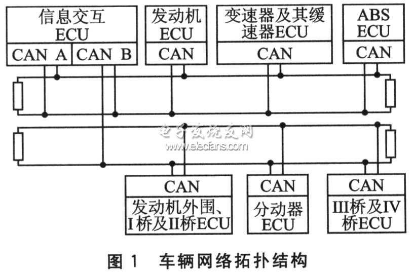
After the ECU products with SAE J1939 CAN interface are connected to the dashboard to form a network, they have basically met the requirements of vehicle driving. In order to make the external communication of the custom ECU as little as possible without affecting the communication between the ECU products, the entire network is divided into two network segments, which can be merged into one network segment if necessary. Segment A contains information interactive ECU, engine ECU, transmission and retarder ECU, ABS ECU; segment B includes information interactive ECU, engine periphery, I bridge and II bridge ECU, transfer ECU, III bridge and IV bridge ECU. The information exchange ECU uses two CAN ports to connect to the two network segments respectively, and has the function of message forwarding. The vehicle network topology is shown in Figure 1.

2 Vehicle network communication design
According to SAE J1939 protocol, vehicle network communication design includes the following aspects:
â—† The physical layer is compatible with SAEJI939-11;
â—† The data link layer is compatible with SAE J1939-21;
â—† The network layer is compatible with SAE J1939-31;
â—† The application layer is compatible with SAE J1939-71;
â—† Application layer diagnosis is compatible with SAE J1939-73;
â—† The network management layer is compatible with SAE J1939-81.
2.1 Physical layer
The physical layer realizes the electrical connection of all ECUs on the network. The physical medium uses shielded twisted pair with a characteristic impedance of 120 Ω, CAN_H is yellow, and CAN_L is green. The network segment uses linear topology as much as possible, and its baud rate is 250 kbps. Both ends of the network trunk are terminated with 120 Ω resistors. The ECU uses short spur lines to connect to the trunk of the network segment, and uses unequal arrangements in the network segment to prevent the generation of standing waves.
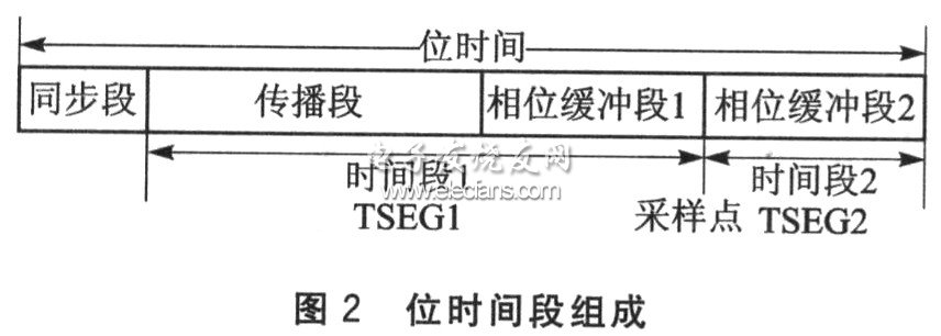
Realize bus management functions such as synchronization, network delay compensation and sampling point position determination within the bit time, and its segment composition is shown in Figure 2. Synchronization is the lengthening of the phase buffer section 1 or the shortening of the phase buffer section 2, and its upper limit is the synchronization jump bandwidth (SJW). The sampling point should be located at (but not exceeding) 7/8 of the bit time as much as possible to achieve the best compromise between propagation delay and clock error. When the clock frequency is 16 MHz, it is recommended that the division factor = 4, SJw = ltq, TSEGl = 13tq, TSEG2 = 2tq (tq is the clock period).

2.2 Data link layer
The data link layer provides a reliable data transmission function above the physical layer and realizes the data exchange of application layer messages. Through the organization of the data link layer, the functions of synchronization, sequence control, error control, flow control, etc., which must be possessed by sending data frames, are realized.
The data link layer organizes protocol-related information in data frames through protocol data units (PDUs). The PDU consists of 29-bit IDs and 0 to 8-byte data fields in the data frame. Its data structure is shown in Figure 3. The P field determines the message priority; the R bit is reserved; the DP bit is the data page bit; the PF field determines the PDU format (PDU1 or PDU2); the PS field is the PDU details, and the PF field determines whether it is the target address DA or the group for PF, Extended GE; SA is the source address.

The messages provided by the data link layer include command messages, request messages, broadcast / response messages, reply messages, and group function messages. In addition, the data link layer also implements the transmission protocol function, which is used to package and reassemble packets larger than 8 bytes and connection management. It is divided into BAM protocol for broadcast announcements and RTS / CTS protocol for point-to-point sessions.
Ningbo Autrends International Trade Co.,Ltd. , https://www.mosvapor.com