Today's integrated circuit (Integrated Circuit, IC) design often requires a chip to include multiple operating modes and work normally at different process corners (corner). The increase in process angles and working modes will undoubtedly make timing closure a great challenge. This article introduces a technology that quickly achieves timing closure in multi-process corners and multi-work modes---MCMM (Multicorner-MulTImode) technology. This technology combines process corners and modes, analyzes and optimizes timing at the same time, and achieves fast To achieve the purpose of timing closure. This technology is applied to the design of a 800,000 gate power network carrier communication (PLC) chip based on TSMC 0.152μm logic technology. The design example shows that the use of MCMM technology can not only solve the problem of difficult timing closure, but also greatly reduce the chip design cycle.
1 IntroductionWith the continuous development of integrated circuit technology, the chip is more and more severely affected by process, voltage, temperature (Process, Voltage, Temperature, PVT), and more process corners are needed to ensure that the chip can work stably under different conditions; At the same time, with the increase in chip test requirements and the enhancement of functions, the working mode of the chip is also increasing, which brings a series of difficulties to the chip layout designer. Of course, the most difficult one is how to quickly achieve timing closure. , Shorten the design cycle. The designer must ensure the timing closure of the chip in the same working mode and different process corners. When the number of process corners and working modes is large, it is not easy to use traditional methods to achieve timing closure, and a lot of manual work is required. Iterate repeatedly, analyze and eliminate the influence between modes, and sometimes it may even be difficult for the timing to converge. The PLC chip designed in our laboratory adopts the MCMM design technology of Synopsis’ IC Compiler software, completely abandoning the traditional timing closure method, effectively accelerating the realization of timing closure and shortening the design cycle.
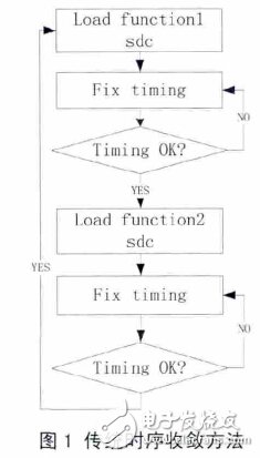
2 Traditional timing closure implementation methodUnder the traditional timing closure and analysis methods, layout design engineers need to switch design constraints back and forth between different working modes for analysis and optimization to meet the timing requirements of the same timing path in different modes, as shown in Figure 1.

It can be seen from Figure 1 that the disadvantage of this method is that the layout tool cannot cover the timing of all modes at the same time. The timing of each mode must be repaired in a serial manner, and it must be ensured that there is no influence between the modes during the repair process. , Which undoubtedly increases the number of iterations of switching between various modes and the time of manual ECO. If the chip has more process corners and modes, the more iterative switching times will be, and the workload will be so large that it is unacceptable for the designer.
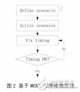
3 Based on MCMM technologyFast timing closure implementation method The basic idea of ​​MCMM technology to achieve timing closure is that the process angle and mode form a scenario (scenario). The layout design software IC Compiler "eats" the timing constraints of all scenarios, activates key scenarios, and allows the software to evaluate and evaluate by itself. optimization. The same offending timing path may appear in different scenarios. Evaluate the timing margin of this offending path in different scenarios. For example, the margin of a path in scenario1 is -1, and the margin in scenario2 is -0.2 , It is considered that it has a higher weight in scenario1, and it is repaired in scenario1 with the highest weight. The specific process is shown in Figure 2.

Obviously, compared with the traditional method, the MCMM technology changes the processing of timing closure from "serial" to "parallel", and the influence between modes is completely handed over to the layout software for analysis, eliminating the need for manual ECO work. , Thereby greatly reducing the number of iterations and design time for timing closure.
4 Application examplesTake a PLC chip in the laboratory as an example, specifically introduce how to use MCMM technology to accelerate timing closure.
4.2 Implementation of timing closure based on MCMM
In the case of activating 10 scenarios at the same time, the server memory overflows, crashes, etc., and the design cannot be carried out smoothly. We have analyzed these 10 scenarios. Among these 4 scenarios, MBIST_MAX, SHIFT_MAX, CAPTURE_MAX, MISSION 60_MAX, the clock frequency is 60MHz in MISSION60_MAX, and the clock frequency of the other three scenarios is only 10MHz, and the setup time margin is all in 9.9ns or more, even if it is not activated during the repair process, the impact of repairing other scenarios is within the tolerance range, and it will not affect the subsequent winding; in the scenario of MISSION90_MAX, the clock frequency is 90MHz, and the setup time Although there is no violation, the margin left is only 0.84ns, which is not enough to withstand the impact of repairing other scenarios; in the remaining 5 scenarios, there are retention time violations and must be repaired. Based on the above analysis, we choose the same
Activate the six key scenarios MISSION90_MAX, MISSION_MIN, MISSION 60_MIN, MBIST_MIN, SHIFT_MIN, CAPTURE_MIN for timing closure. The specific scripts are as follows: set_acTIve_scenarios {MISSION90_MAX MISSION90_MIN MISSION60_MIN MBIST_MIN SHIFT_cenarios for each critical scenario all cenFT_cenarios]
current_scenario scenario set_clock_uncertainty -hold 0.2 [all_clocks]set_clock_uncertainty -setup 0.6 [all_clocks] set_prefer -min{tcb0152gbwp7twc/DEL015BWP7Ttcb0152gbwp7twc/DEL02BWP7T}set_fix_fix_fix_opdarios set_fix_hold_fix_opd cell to fix hold timing) update_clock_latency (update clock delay) psynopt (to fix timing)
4.3 Result analysis
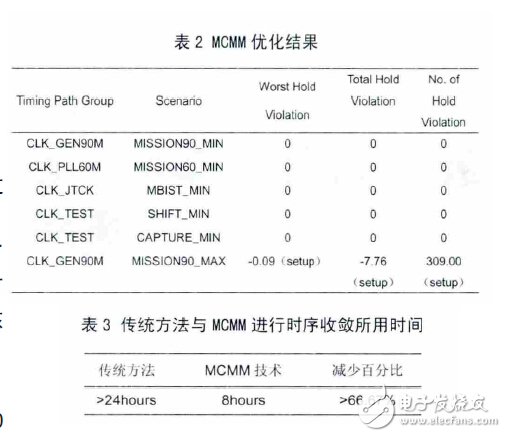
After the above operations, the timing paths of the 6 scenarios are optimized at the same time, and the results are shown in Table 2.
The results in Table 2 show that almost all modes have met the timing requirements. Only the scenario of MISSION90_MAX has a setup timing violation. In order to fix the violation, you only need to activate the scenario and “psynopt†again to reach the timing requirements.
We also tried to use traditional methods to repair the timing of the chip. Due to the large number of modes, the number of switching back and forth between the modes was more than 20 times. In addition, the timing interference between the modes was serious, and the manual analysis workload was very large, which was required for timing closure. The time spent is much longer than the time spent using MCMM technology. The advantages of MCMM technology are very obvious. The specific results are shown in Table 3.

This article introduces IC Compiler's MCMM synchronization optimization technology, and uses a design example to illustrate the specific implementation process of the technology. The results show that the design time is greatly saved, and it also solves the problem of manual analysis intervention for layout design engineers, which has certain practical application value. . In the design process, we started to use MCMM technology after the CTS stage to achieve the purpose of chip timing closure. In the future more complex and demanding designs, we will apply MCMM technology to some key steps, such as logic synthesis and place. , And comprehensively consider the power consumption of the chip.
4.1 Definition of scenario
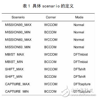
The chip has 2 normal working modes, the clock frequency is 90Mhz and 60Mhz, and the 3 DFT test modes are shift mode, capture mode and mbist mode. It needs to work in two process corners, WCCOM and BCCOM, which is 5 The two process corners of this model form 10 scenarios, and each scenario specifies the corresponding parasitic model (TLU+ file), worst and best, as shown in Table 1. Check the setup time under the WCCOM process corner, and check the hold time under the BCCOM process corner.

The specific script that defines the scenario is as follows:
create_scenario MISSION90_MAX (create a scenario named MISSION90_MAXX) set_operating_conditions \
-analysis_typeon_chip_variation \-max_library tcb0152gbwp7twc \-max WCCOM (specify timing analysis type and lib library under the corresponding corner) set_tlu_plus_files \-max_tluplus ./test/cl0152g_lp6m_worst.tlup \-tech2itf_map ./tech2itf_map RC parasitic model of corner) source. /netlist /KOALA_ASIC_TOP_compiled_pass3_mission_90_mode_post.sdc (read in the timing constraint file for this mode).
Safety Light Curtain,Safety Curtain,Laser Safety Light Curtain,Safety Optic Light Curtain,Security Light Curtain,Press Brake Safety Light Curtains
Jining KeLi Photoelectronic Industrial Co.,Ltd , https://www.sdkelien.com