Overview:
This paper presents a design scheme for a simple transmissive visibility and CO2 concentration measuring device. The program introduces the basic measurement principle, hardware circuit diagram and software flow chart of the designed device. At the same time, the experiment verified its performance in measuring visibility and CO2 concentration. This proves that the device designed by this scheme not only has convenient measurement, but also has the advantages of economy, practicality and portability.
0 Introduction Visibility is the visible distance of the target. It refers to the maximum distance that can be distinguished from the background when the target is observed. In recent years, due to various reasons, the visibility of the atmosphere in the world is getting lower and lower, the greenhouse effect is becoming more and more obvious, and smog and dust storms have become hot topics. The production of national defense industry and the daily life of the people have been greatly affected. Strengthening the measurement of CO2 and visibility in the air is imminent.
At present, the visibility instruments that have been developed in the world have two types of transmission and scattering, and the research on visibility measuring instruments in China is not yet mature.
This paper presents a simple design of a transmissive visibility measuring device with CO2 detection. Using single-chip control, the measurement and display are integrated, the instrument is simple and practical, and the measurement results are clear at a glance. The volume is small and easy to carry, the data is real-time and the flexibility is large. The experiment verified that the program basically meets the needs of daily life.
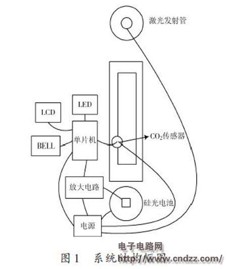
1 Measuring device principle and structure block diagram The device includes a visibility measurement system and a CO2 measurement system, as shown in Figure 1. 
The attenuation of light is caused by the scattering and absorption of particles along the beam path. In the visibility measurement system, the laser emitting tube emits laser light, and the silicon photocell detects the light transmittance of the horizontal air column in the sampling space, and the optical signal is converted into a voltage signal. At this time, the change of voltage reflects the change of visibility. The device controls a plurality of LED lights through a single-chip microcomputer to directly reflect the visibility of the measured environment. In the CO2 measurement system, the CO2 sensor uses MG811, which uses the principle of solid electrolyte battery to sample the potential difference (EMF) between the sensor's sensitive electrode and the reference electrode. The potential difference is amplified and temperature compensated into the microcontroller, and the formula is corrected and converted to CO2 concentration. And through the LCD screen display, use a buzzer to alarm the high concentration of CO2 conditions.
(Please read the PDF for details)
Homemade library ground wave TV double ring indoor antenna: The received ground decimeter wave frequencies are currently in the 500-800 MHZ frequency range. If there is a good field strength in the urban area, low frequency and high frequency should be taken into account. This is the best resonance; The frequency center is around 700MHz, which is converted according to the radio propagation speed and frequency. If the center frequency wavelength is about 42cm, then the diameter of the ring antenna should be 13cm, that is, the diameter should be a quarter of the center frequency wavelength of about 42cm. If we think of a 42cm conductor as a ring with a central frequency and wavelength of 42cm, then its diameter should be close to 13cm. If we make a good antenna, we can get twice the result of receiving ground waves with half the effort!
Indoor Antenna for TV ,Indoor Antenna Walmart,Indoor Antenna Best,Indoor Antenna for Router ,Indoor Antenna for Booster
Yetnorson Antenna Co., Ltd. , https://www.yetnorson.com