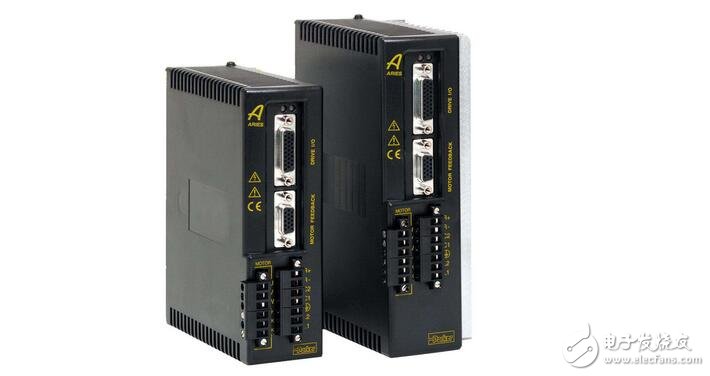
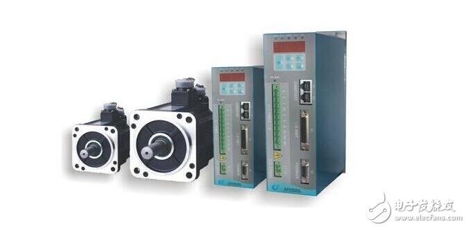
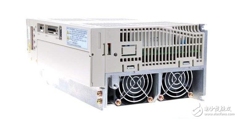
Servo drives, also known as "servo controllers" and "servo amplifiers", are controllers used to control servo motors. They act like a frequency converter acting on a common AC motor and are part of the servo system. Mainly used in high precision positioning systems. Generally, the servo motor is controlled by three modes: position, speed and torque to realize high-precision transmission system positioning. At present, it is a high-end product of transmission technology.

At present, the mainstream servo drivers adopt digital signal processor (DSP) as the control core, which can realize more complicated control algorithms, realize digitalization, networking and intelligence. The power device generally adopts the driving circuit designed with the intelligent power module (IPM) as the core. The IPM integrates the driving circuit internally, and has fault detection and protection circuits such as overvoltage, overcurrent, overheat and undervoltage, and adds soft in the main loop. Start the circuit to reduce the impact of the startup process on the drive.

The power driving unit first rectifies the input three-phase electric power or the commercial power through a three-phase full-bridge rectifying circuit to obtain a corresponding direct current power. After rectifying the three-phase electric or commercial power, the three-phase permanent-magnet synchronous AC servo motor is driven by the three-phase sinusoidal PWM voltage inverter. The entire process of the power drive unit can be simply the process of AC-DC-AC. The main topology circuit of the rectifier unit (AC-DC) is a three-phase full-bridge uncontrolled rectifier circuit.
With the large-scale application of servo system, servo drive use, servo drive debugging and servo drive repair are all important technical issues of servo drives. More and more industrial control service providers have carried out in-depth technical research on servo drives.
Servo drives are an important part of modern motion control and are widely used in automation equipment such as industrial robots and CNC machining centers. Especially for servo drives for controlling AC permanent magnet synchronous motors, it has become a research hotspot at home and abroad. The current, servo, and position 3 closed-loop control algorithms based on vector control are commonly used in current AC servo drive design. The speed closed-loop design in this algorithm is reasonable or not, which plays a key role in the performance of the entire servo control system, especially the speed control performance.

The general servo has three control modes: position control mode, torque control mode, and speed control mode.
1. Position control: The position control mode generally determines the rotation speed by the frequency of the externally input pulse. The number of pulses is used to determine the angle of rotation. Some servos can directly assign speed and displacement through communication. Since the position mode has strict control over speed and position, it is generally applied to positioning devices.
2. Torque control: The torque control mode is to set the external output torque of the motor shaft through the external analog input or the assignment of the direct address. The setting can be changed by changing the analog setting in real time. The magnitude of the torque can also be achieved by changing the value of the corresponding address by means of communication.
The application is mainly in the winding and unwinding devices that have strict requirements on the material, such as the winding device or the fiber-optic device. The torque setting is changed according to the change of the radius of the winding to ensure the stress of the material. It will change as the winding radius changes.
3. Speed ​​mode: The rotation speed can be controlled by the analog input or the frequency of the pulse. The speed mode can also be positioned when the outer ring PID of the upper control device is controlled, but the position signal or direct load of the motor must be used. The position signal is given to the upper feedback for calculation. The position mode also supports the direct load outer loop detection position signal. At this time, the encoder at the motor shaft end only detects the motor speed, and the position signal is provided by the direct final load end detection device. This has the advantage of reducing the intermediate transmission process. The error increases the positioning accuracy of the entire system.
If there is no requirement for the speed and position of the motor, as long as a constant torque is output, of course, the torque mode is used.
If there is a certain accuracy requirement for position and speed, and the real-time torque is not very concerned, it is not convenient to use the torque mode, and the speed or position mode is better.
If the host controller has a better closed-loop control function, the speed control effect will be better. If the requirements are not very high, or there is basically no real-time requirement, the position control mode is adopted.

The main control method of the servo drive to the motor
The main control methods of the servo drive to the motor are: position control, speed control and torque control.
Position control: It means that the speed, rotation angle and torque of the motor are controlled by the driver. The upper computer controls the speed and rotation angle of the pulse train of the driver. The input pulse frequency controls the speed of the motor. The number of pulses input controls the motor rotation. Angle.
Speed ​​control: It means that the drive only controls the speed and torque of the motor. The angle of the motor is controlled by the A, B, and Z encoder signals fed back by the CNC. The CNC sends an analog (voltage) signal to the driver. The range is +10V~-10V, the positive voltage controls the motor to rotate forward, the negative voltage controls the motor to reverse, and the magnitude of the voltage determines the number of revolutions of the motor.
Torque control: It means that the servo drive only controls the torque of the motor. The torque output by the motor does not change with the load. It only listens to the input torque command. The upper computer sends an analog (voltage) signal to the driver. The range is +10V~-10V, the positive voltage controls the motor to rotate forward, the negative voltage controls the motor to reverse, and the magnitude of the voltage determines the torque output by the motor. The speed and rotation angle of the motor are controlled by the host computer.
KNL6,KNL8 Residual Current Circuit Breaker
KNL6,KNL8 Moulded Case Circuit Breaker is MCCB , How to select good Molded Case Circuit Breaker suppliers? Korlen electric is your first choice. All moulded Case Circuit Breakers pass the CE.CB.SEMKO.SIRIM etc. Certificates.
Moulded Case Circuit Breaker /MCCB can be used to distribute electric power and protect power equipment against overload and short-current, and can change the circuit and start motor infrequently. The application of Moulded Case Circuit Breaker /MCCB is industrial.
Korlen electric also provide Miniature Circuit Breaker /MCB. Residual Current Circuit Breaker /RCCB. RCBO. Led light and so on .
KNL6,KNL8 Molded Case Circuit Breaker,Small Size Molded Case Circuit Breaker,Electrical Molded Case Circuit Breaker,Automatic Molded Case Circuit Breaker
Wenzhou Korlen Electric Appliances Co., Ltd. , https://www.zjaccontactor.com