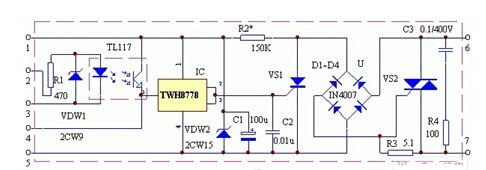

The working principle of the multi-sensitive solid-state controller: The design concept of the device is to control the high power with micro power, and can convert the non-electricity signal of nature into automatic control of electric signal. It should have high control sensitivity, but it is not easy to produce errors. Action, when doing general control applications, no additional control power is required; when used with external equipment, it should have good isolation. It is required to work without sparks, no noise, good explosion-proof performance, long life, low cost and good versatility. The block diagram of the internal circuit of the device is shown in the first figure. Its internal circuit works as shown in the second picture. It has 7 pins: 6 is the load end, 7 is the AC output, 1 is the positive end of the control power, 2, 3 is the isolator input, 4 is the passive control, 5 is the control power Negative terminal. The internal circuit of the device is composed of a photocoupler TIL117, a trigger drive switch integrated circuit TWH8778, a rectified full bridge U, and a triac VS2. When the unidirectional thyristor VS1 is judged, there is no current loop in the full bridge circuit U, so there is no current output, and the triac VS2 has no trigger current and is cut off, thereby blocking the load current. Since the trigger pole of VS1 is connected to the output of the switch integrated circuit TWH8778, the on/off of the TWH8778 controls the turn-on and turn-off of VS1.
The resistor R2, the capacitor C1 and the Zener diode DW2 form a low-voltage DC regulated power supply for the TWH8778. Therefore, by adding a control voltage greater than 1.6V to the 4 pin of the controller, the TWH8778 can be turned on. After the TWH8778 is turned on, its output terminals 2 and 3 become high level, triggering VS1 to turn it on, so the full-bridge rectifier circuit composed of diodes VD1-VD4 is turned on, and there are positive and negative at this time. The pulse voltage in both directions triggers the G pole of the triac VS to turn on VS2, which drives the load to work. The voltage at the 4-pin of the control terminal can be completely provided by the 1 terminal of the controller DM, so no external control power supply is required. This is the basic condition that constitutes passive control. The 2nd and 3rd pins of the controller DM are the photoelectric isolation control input terminals. When the phototransistor in the usual photocoupler TIL117 has no light, its internal resistance is extremely high, which is equivalent to an open circuit. Once the control voltage is applied to pins 2 and 3 of the DM, the LEDs in the TIL117 are illuminated, and the illumination causes the internal resistance of the phototransistor to drop rapidly, resulting in sufficient current to pass through the ce pole of the phototransistor to trigger the 5 feet of the TWH8778. Can control the load work. R1 is the input current limiting resistor. DW1 is an input voltage limiting diode with a regulation value between 1.5 and 2V, so that the optocoupler TIL117 is not damaged even if the input voltage exceeds a predetermined value.
Air Humidifier,Ultrasonic Air Humidifier,Air Humidifier For Home,Mini Usb Air Humidifier
Dongguan Yuhua Electronic Plastic Technology Co.,Ltd , https://www.yuhuaportablefan.com