Abstract: The function and classification of power control technology are briefly described, the power control technology scheme of the bandwidth CDMA system is introduced, the implementation constraints are discussed, several key factors affecting performance are simulated, and the hardware implementation and test results are given. .
The service provided by the wireless cellular network for each user needs to meet a certain quality of service (QOS). However, QOS is mainly determined by the signal-to-interference ratio (SIR) of the signal received by each user. Therefore, the wireless cellular network's allocation of wireless resources, especially the power allocation of each user link, is even more important. For CDMA cellular systems, all users in the same cell use the same frequency band and time slot, and users are isolated from each other only by the (quasi) orthogonal characteristics of spreading codes. However, due to the multipath and delay of the wireless channel, the cross-correlation characteristics between the signals of various users are not ideal. The signals of other users interfere with the current user signals. This type of interference is called multiple access interference (MAI). In this way, when the number of users in the cell increases or the power of other users increases, the interference to the current user will increase, resulting in a decrease in the received signal SIR of the current user. When such interference is large to a certain extent, the current user cannot communicate normally. Therefore, the CDMA system is a severe interference limited system, and the size of the interference directly affects the system capacity. There are two main ways to solve this problem: multi-user detection technology and power control technology. The multi-user detection technology fully considers the MAI existing between users, and reconstructs these interferences at the receiving end, and then eliminates its influence to improve performance. However, because its algorithm is too complicated, it has not been commercialized yet. The power control technology is very simple and practical, and is considered to be one of the key technologies of the CDMA system. Power control technology adjusts the transmission power of each user, compensates for channel fading, offsets the near-far effect, and maintains each user at the minimum standard that can maintain normal communication. This can minimize interference with other users and thereby increase system capacity. At the same time extend the standby time of the phone. 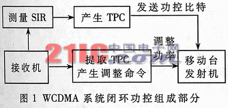
The control criteria of power control technology can be roughly divided into two categories: power balance criteria and SIR balance criteria. They control the useful power or SIR of each user signal at the receiving end to be equal. Thus, from different angles, there can be different power control technology classification. According to the power control effect, it can be divided into inner loop power control and outer loop power control. The inner loop power control is mainly used to combat channel fading and loss, so that the signal SIR or power of the receiving end reaches a specific target value; the outer loop power control generates the SIR or power threshold of the inner loop power control according to the service quality requirements in a specific environment value. According to the link, it can be divided into reverse power control and forward power control. Since the capacity of the CDMA system is mainly limited by the capacity of the reverse link, reverse power control is particularly important. The loop type of power control can be divided into open-loop and closed-loop power control. Open-loop power control is based on the assumption of uplink and downlink channel symmetry. It can offset path loss and shadow fading. Closed-loop power control does not need to make this assumption. It also It can also offset fast decline. According to the way of power control implementation, it can be divided into centralized power control and distributed power control. Centralized power control considers the information (link gain, etc.) of all users in the cell and uniformly adjusts each user. The complexity of this algorithm High, difficult to achieve, but the algorithm has good convergence characteristics; distributed control only generates control instructions based on individual user information, which is easy to implement, but distributed algorithms need to meet certain conditions to converge.
1 WCDMA system power control technical solution
WCDMA system also uses reverse open loop, closed loop, outer loop power control technology and forward closed loop, outer loop power control technology. In view of the importance and space limitation of reverse closed-loop power control, this article will mainly discuss reverse closed-loop power control. The following simulation curve is also based on reverse closed-loop power control. The closed loop control of WCDMA system is mainly composed of four parts: SIR estimation, power control bit (TPC) generation, local TPC decision and power high-speed unit, etc., as shown in Figure 1.
The SIR estimation unit uses a certain SIR estimation algorithm to estimate the SIR of the receiving dedicated data channel (DPDCH), and then sends the estimated value to the TPC generation unit. The WCDMA protocol does not specify an algorithm for SIR estimation. There are two main algorithms: coherent SIR estimation and non-coherent SIR estimation. The performance difference between these two methods will be analyzed later. In addition, another major factor that limits the accuracy of SIR estimation is the length of SIR estimation, that is, the number of samples that can be used to estimate. For non-coherent estimation, there are more samples and less coherent estimation samples. The timing relationship of power control is limited. The TPC generating unit subtracts the SIR estimated value SIResTI and the SIR reference threshold SIRtarget generated by the outer loop power control, and generates TPC bits according to the sign of the difference, that is, sign (SIResTI-SIRtarget). The TPC decision unit regenerates the local TPC command according to the locally received TPC bits and sends it to the power control adjustment unit for adjusting the transmit power of the forward or reverse channel. The literature gives several algorithms for local TPC command generation in WCDMA system, of which there are two algorithms in the non-macrodiversity state. 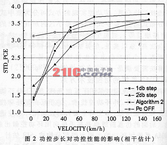
Algorithm one, for the TPC command received in the current slot, each slot generates a TPC_cmd.
If the received TPC command is equal to 0, then the TPC_cmd of this time slot is -1.
If the received TPC command is equal to 1, then the TPC_cmd of this time slot is 1.
Algorithm 2: In the first 4 time slots of 5 time slots, TPC_cmd = 0, that is, the transmission power is not changed. In the 5th time slot, the following hard decisions are applied to the 5 TPC commands received:
If the hardware decision for all 5 TPC commands is 1, then TPC_cmd = 1 for the 5th time slot
If the hard decisions of all 5 TPC commands are 0, then TPC_cmd = -1 for the 5th time slot
Otherwise, TPC_cmd = 0 in the 5th time slot.
It can be seen that algorithm one generates a power control command (± 1) in each time slot, and the frequency of power adjustment is 1.5 kHz. Algorithm 2 generates a power control command (± 1) every 5 time slots. The fastest frequency for power adjustment is 300Hz. It has a performance of nearly 0.2dB (1dB / 5) power control step size. Algorithm 2 also has the function of preventing misadjustment of power control. When the received power control bits are exchanged by ± 1, the generated power control command is always 0, so that no power adjustment is performed. Based on the previous transmission power p [k-1], the power adjustment unit adjusts the current transmission power p [k] [dB] according to the following kth TPC command according to the following formula:
p [k] = p [k-1] + β.TPC_cmd (1)
Among them, β is the power control step size, WCDMA system uses a fixed step size, forward power control uses 0.5, 1, 1.5 or 2db four steps, reverse power control uses 1 or 2dB two steps, and TPC_cmd is local The generated TPC command.
The WCDMA standard stipulates that the power control rate is 1.5kHz, that is, a closed-loop power adjustment must be completed within a time slot, which requires all the above power control operations to be completed within a certain time. Figure B.1 in the literature lists the timing relationship of WCDMA power control, and the time available for SIR estimation after analysis is:
TSIR = 2560 + Tdata1-1024-2 & TImes; Tprop-Tprocess (2)
Tprocess is the receiver processing delay, 2 & TImes; Tprop is the two-way path delay, and the processing delay is generally equal to the total path delay. If data1 data processing delay Tdata1 is ignored, the estimated SIR time is roughly:
TSIR = 1536-4 × Tprop (3)
When the one-way delay Tprop ≥ 384chips, the corresponding cell radius is greater than 30km, the base station has no time to complete the SIR estimation and send power control bits in the current time slot. At this time, a time slot must be delayed for SIR estimation and power control bits are sent. At this time, a 750 Hz power control scheme that delays one time slot for SIR estimation must be used. 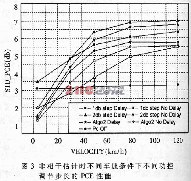
2 WCDMA system power control performance simulation
This section will explain the influence of main factors such as SIR estimation method, estimation accuracy, step size selection, power control bit transmission error, and power control bit delay on the power control performance through computer simulation methods, and give the reverse closed-loop power control. Simulate the curve and make some analysis and interpretation of the results.
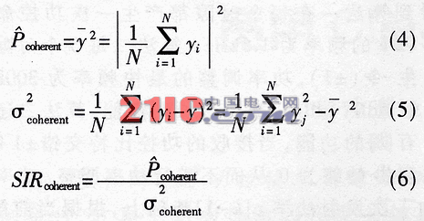
First analyze the two methods of SIR estimation, the principle of coherent estimation and non-coherent estimation. For coherent estimation, since the pilot signal is known, assuming that the pilot sequence value is fixed at 1, the received signal y (i) is approximately a Gaussian stationary random process, and its time average can be used to replace the set average. Assuming that the N sampling points of the received signal y (i) are {y1, y2, y3,…, yn}, the estimated values ​​of the received signal power, crying power, and signal-to-interference ratio can be expressed as follows:
When non-coherent estimation is used, the processed data is no longer a known pilot signal, but data on a data channel whose value is unknown. The following methods can be used to estimate the signal-to-interference ratio: 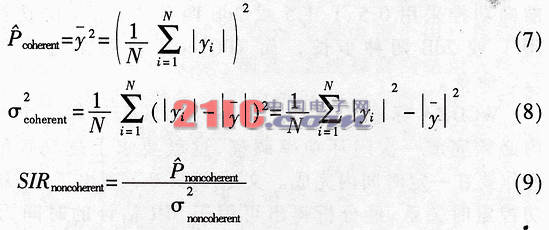
When the coherent estimation and non-coherent estimation have the same number of estimated samples, the performance of coherent estimation is better than that of non-coherent estimation. From the timing constraint analysis in the previous section, it can be seen that the number of samples for coherent estimation is limited by factors such as cell radius, and the performance of coherent estimation deteriorates seriously when the number of samples is too small. Although non-coherent estimation can obtain more estimation samples, its performance is also restricted by many factors. The literature has studied in detail the problem of non-coherent estimation algorithms, and concluded that the coherent SIR estimation algorithm has more incoherence than incoherent estimation in most cases. It is estimated that the better performance, the subsequent simulation results will also illustrate this problem.
The goal of closed-loop power control is to control the actual signal-to-interference ratio of the received signal at the target value, so the most direct way to measure the performance of the algorithm is to examine the perfection of the actual signal-to-interference ratio and the target signal-to-interference ratio. The error (PCE) is as follows:
PCE = SIResti-SIRtanget (10)
Use it to measure the performance of various power control algorithms. The literature proves that under ideal power control, the logarithm of PCE is normally distributed, and its mean value is zero. The mean square error reflects the merits of the power control algorithm. The smaller the mean square error, the better the power control algorithm.
Figure 2 shows the PCE performance of coherent estimation, different vehicle speed conditions, and different power control adjustment steps. It can be seen that at low speeds, the algorithm with 1dB step size is better, and the algorithm is second, and the algorithm with 2dB step size at medium speed is better, and the performance of the three is worse at high speed. Figure 2 also shows the mean square deviation of PCE without power control. Below 80km / h, power control can bring benefits. Above this speed, from the perspective of PCE, power control cannot bring gain. Too. It can be concluded that in the fixed step algorithm, 1dB step is used at low speed, 2dB or 1db step is used at medium speed, and although fast fading cannot be compensated at high speed, but considering the compensation of path loss and reduction to other users In this case, the algorithm 2 should be used for slow power adjustment.
Figure 3 shows the PCE performance of different power control adjustment steps under different vehicle speeds under incoherent estimation. The length of the non-coherent estimate here is the entire time slot, so a method of delaying one time slot for power control is used. For comparison, the performance of incoherent estimation with the same estimated length but no delay is also drawn. It can be seen that when the non-coherent estimation method is used, the relationship between the vehicle speed and the optimal step size is similar to that when the coherent estimation method is used. It is worth noting that only at low speeds of about 20km / h, the performance of PCE is worse than when power control is turned off, and when the coherent estimation method is used, this critical speed reaches more than 80km / h. From this, it can be concluded that the performance of the non-coherent estimation algorithm is worse than the coherent estimation. Therefore, all subsequent simulations use coherent SIR estimation algorithms. 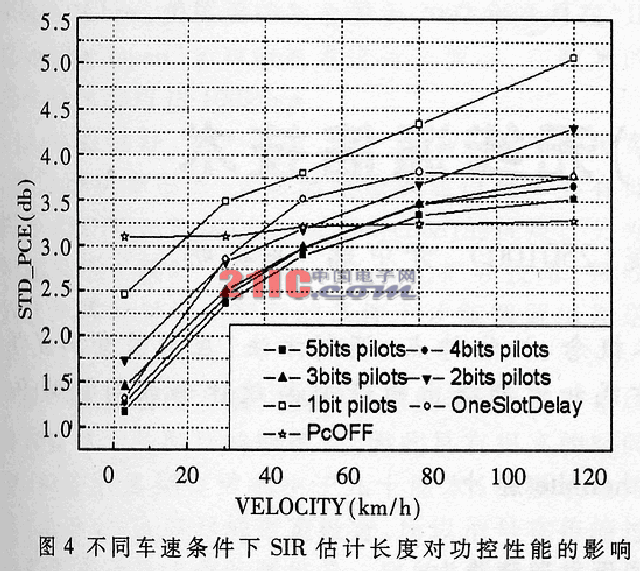
It can be seen from the above simulation results: under different vehicle speed conditions, if you want the best power control performance, you need different adjustment steps. Therefore, in order to improve the performance of power control, a natural idea is to select the optimal power control step at the speed of the vehicle by estimating the vehicle speed. The literature discusses this problem, and simulates the construction of new variables, level passing rate and blind estimation of variable step size and other algorithms, which can achieve a certain performance gain.
Figure 4 shows the effect of SIR estimated length on power control performance under different vehicle speeds. Obviously, the larger the estimated length of coherence, the better the performance. As can be seen from Figure 4, the estimated length is between 3 and 5 pilot bits, that is, 768 to 1280 chips, the performance difference of power control is not large; if the estimated length is only 2 bits, that is, 512 chips, the performance change is relatively large; if only 1 bits, that is The estimated length of 256chips, performance degradation is very severe, even worse than the performance when power control is turned off. It can also be seen from FIG. 4 that if the cell radius is too large, it is impossible to complete SIR coherent estimation and a closed-loop power adjustment in a time slot, and the power control frequency can be reduced at this time. In this way, although there is a time slot delay for power adjustment, the high-precision SIR estimation obtained thereby can offset the performance loss caused by the delay in a certain procedure. It can be seen from Figure 4 that this scheme has almost the same performance with no delay and an estimated length of 512 chips. Therefore, when the cell radius is small, the 1.5 kHz power control scheme should be used and the longest possible SIR estimated length should be used. When the cell radius is large and the mobile station is at the edge of the cell, the 750 Hz power control scheme can be used.
In addition, the performance loss caused by the power control bit delay can also be compensated by the delay compensation (TDC) method. The literature has studied this problem in detail. Here is a useful conclusion. In the case of a power control delay of one time slot, the effect of power control bit delay is not large at low and medium speeds, and the effect is more obvious at high speeds. This is because the power control frequency of 750 Hz is no longer possible at high speeds Track fast channel changes, but at this time it should also be able to compensate for path loss. Therefore, when the 750 Hz power control scheme is required, if the mobile station is in a high-speed motion state, it is best to use algorithmic binary slow power adjustment at this time. 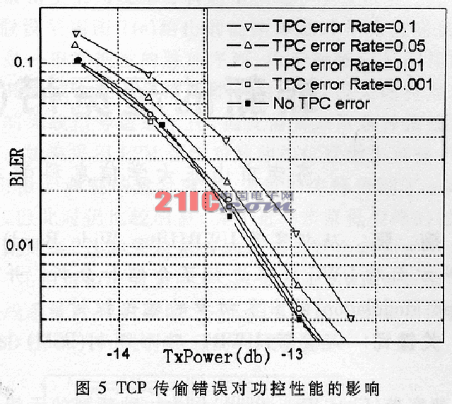
Figure 5 shows the BLER performance for a 3km / h, three-path fading channel with a TPC transmission error rate from 0.001 to 0.1. It can be seen from FIG. 5 that when the TPC error rate is low, for example, below 0.01, the performance does not deteriorate significantly, and if the TPC error rate continues to increase, for example, when it reaches 0.1, the performance will deteriorate by 0.3 to 0.5 dB. If you consider the typical situation, that is, the symbol error rate of the forward link is 0.05, you can see that the performance degradation is large, reaching about 0.2dB. At this time, the quality of the forward link has already produced a large impact on the reverse closed-loop power control performance. influences. It can be seen that the performance of closed-loop power control is affected by two links at the same time, and improving the performance of one link will bring gain to the other link, and vice versa.
3 FPGA implementation of WCDMA system power control
In the previous section, several main factors affecting power control performance were simulated, which provided useful help for designing a WCDMA system control scheme. According to the previous simulation structure, the author chose reasonable parameters and designed the forward and reverse closed-loop power control module of the WCDMA system based on the FPGA platform. This design uses Verilog code as the hardware description language, uses Cadence's NC-SIM simulator for verification, and finally uses Xilinx's ISE6.1i integrated environment for comprehensive wiring, downloads to Xilinx's Virtex II-6000E series FPGA device platform WCDMA system reverse and forward link closed-loop power control function. This design verified the correctness of the design in the joint debugging test of the WCDMA system mobile station and base station. It can control the transmission power of the front and reverse links well during voice and data communication. At the same time, this design also cooperates with Anritsu. The WCDMA signaling tester MD8480B was jointly debugged, and the correctness of the design function was also verified.
High Voltage Capacitor,Igh Voltage Variable Capacitor,High Voltage Electrolytic Capacitors,High Voltage Capacitor Leakage Tester
Yangzhou IdealTek Electronics Co., Ltd. , https://www.idealtekpower.com