"Control Loop Design for Linear and Switching Power Supplies" is the latest work by Christophe Basso, a former columnist at Power Electronics. This work focuses on the knowledge that engineers really need to understand to compensate and stabilize a given control system. This contains an excerpt from the book on stability standards.
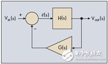
In the electronics field, an oscillator is a circuit that produces a self-excited sinusoidal signal. In a wide variety of configurations, the acceleration process of the oscillator involves the noise inherent in the electronic circuitry that uses the oscillator. At the time of power-on, the noise level rises, and at this time, oscillation and self-excitation begin. Such a circuit can be composed of the constituent modules shown in FIG. As you can see, this configuration looks very close to the configuration of our control system.

Figure 1: The oscillator is essentially an error signal that does not interfere with the control system of the output signal.
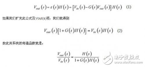
In our example, the excitation input is not noise, but the voltage level Vin, which is injected as an input variable to start the oscillator. The direct channel consists of the transfer function H(s) and the return channel contains the G(s) block. To analyze this system, we first write its transfer function by the equation of the relationship between the output voltage and the input variable:

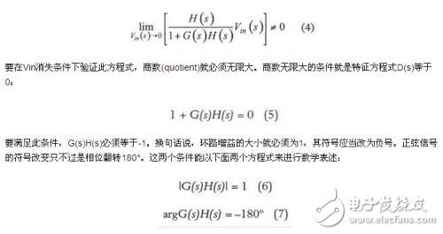
In this equation, the product G(s)H(s) is called the loop gain, which is labeled T(s). To convert our system to a self-excited oscillator, there must be an output signal even if the input signal has disappeared. In order to meet such a goal, the following conditions must be met:


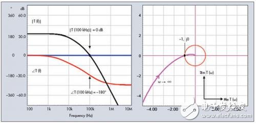
Figure 2: The oscillation conditions can be expressed in Bode plot or Nyquist plot.
Under the condition that these two equations are satisfied, we obtain the steady-state oscillation condition. This is the so-called Barkhausen standard, proposed by the German physicist Barkhause in 1921. In fact, in a control loop system, it means that the correction signal no longer resists the output, but returns in phase form with the same amplitude as the excitation signal. Equations (6) and (7) represent the loop gain curve in the Bode plot, which passes through the 0 dB axis and is affected by the 180° phase lag just at this point. In the Nyquist analysis, the relationship between the imaginary number of the loop gain and the relative frequency of the real part is plotted as a graph, which corresponds to -1, j0. Figure 2 shows two curves that satisfy the oscillation conditions. If the system deviates slightly from these values ​​(such as temperature drift, gain variation), the output oscillation will either drop exponentially to zero or the amplitude diverges until a higher or lower power rail is reached. In the oscillator, the designer tries to reduce the gain margin as much as possible so that the oscillation conditions can be satisfied under a variety of operating conditions.
Stable condition
As you know, the goal of the control system is not to build an oscillator. We want the control system to provide high speed, accurate and non-oscillating response. Therefore, we must avoid configurations that satisfy the oscillation or divergence conditions. One way is to limit the range of frequencies in which the system will react. By definition, the frequency range or bandwidth corresponds to a frequency that is 3 dB lower than the closed loop transmission channel from input to output. The bandwidth of a closed loop system can be viewed as a range of frequencies within which the system is considered to respond very well to its input (ie, to follow set points or to effectively suppress disturbances). As we will see later, in the design phase, we do not directly control the closed loop bandwidth, but control the crossover frequency fc - a parameter related to open loop analysis. These two variables are usually roughly considered equal, but we will see that this is only true under one condition. However, they are not too far apart, and the two can be interchanged in the discussion.
We have seen that the open loop gain is an important parameter in our system. When the gain is present (ie |T(s)|â€1), the system operates with a dynamic closed loop that compensates for input disturbances or reacts to setpoint changes. However, there are limits to the system response: the system must provide a gain at the frequency involved in the disturbance signal. If the disturbance of the setpoint change is too fast, the frequency component of the excitation signal is lower than the system bandwidth, indicating that these frequencies lack gain: the system slows down and does not react, and the operating state is like a loop that does not respond to waveform changes. So, is it asking for infinite bandwidth? No, because increasing bandwidth is like widening the diameter of the funnel: you can of course collect more information and react faster to input vibration, but the system will also receive spurious signals, such as converters. In some cases, the noise and parasitic parameters generated by itself (such as the output chopping in the switching power supply). Therefore, it is mandatory to limit the bandwidth to what your application really requires. Using too wide a bandwidth will impair the system's noise immunity (eg, it suppresses the robustness of external spurious signals).
Cordline Switches,Electrical Switch,Rocker Switch,Foot Switch,on off switches
Jiangmen Krealux Electrical Appliances Co.,Ltd. , https://www.krealux-online.com