Reducing optical transmission costs is a common goal of communication system providers and network operators. Intense competition within the industry has been a major driver of lowering costs. However, recently, in order to prove that the transition from 10G to 40G is an inevitable trend in the industry, the cost issue has received more and more attention.
In this article, we will introduce how Fiber Bragg Grating (FBG) dispersion compensation technology supports new low-cost amplifier designs and new applications, thus taking a big step toward the dream of reducing costs.
FBG and dispersion compensation fiber
There is a fundamental difference between the traditional way of using FBG reflection for dispersion compensation and for compensation using Dispersion Compensating Fiber (DCF). The basic principle of dispersion management through FBG is to introduce different delays for different wavelengths using an accurate chirped fiber grating. A grating can be specifically fabricated to simulate the dispersion characteristics of the fiber or a span. (see picture 1)
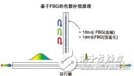
Figure 1. The grating introduces different delays for different wavelengths. The precision chirped grating is used to simulate the dispersion characteristics of the compensated fiber.
There are many obvious advantages to using FBG for dispersion compensation compared to the traditional DCF method. However, this article mainly describes several features of FBG that directly lead to new amplifier designs and architectures.
The most well-known and significant advantage of the FBG Dispersion Compensation Module (FBG-DCM) is its low insertion loss. In general, the FBG-DCM insertion loss of 120km is 3 to 4dB, and the insertion loss of the equivalent DCF is about 10dB or even higher. Moreover, the insertion loss and transmission span of FBG-DCM are almost independent, while the insertion loss of DCF-DCM increases with the increase of fiber and transmission span.
This distance independence, in addition to the better module package form, also leads to another major advantage of FBG-DCM compared to DCF-DCM, which is the hysteresis time, which is the delay caused by the optical signal entering and leaving a device. For passive dispersion compensation devices, the hysteresis time is proportional to the optical path length in the device.
The 100 millisecond hysteresis time is common for DCF-DCM, while the FBG-DCM hysteresis time is three orders of magnitude smaller, which is negligible in most practical applications.
Another feature of FBG-DCM that is significantly better than DCF-DCM is that it does not produce nonlinear effects when inputting large optical power. Although the optical power generated by DCF-DCM due to nonlinear effects is not large, it is generally less than -2dBm per channel. However, FBG-DCM technology does not introduce nonlinear effects at the highest power of any current optical network.
The insertion loss is small, the hysteresis time is negligible, there is no nonlinear effect at high power, and the important characteristics of these FBG-DCMs are not only improve the structure of the amplifier, but also play a significant role in reducing the overall cost of the system.
Intermediate access EDFA design
Taking advantage of the features of FBG-DCM, traditional EDFAs can be optimized in a number of ways. Not only performance, such as noise figure, can be greatly improved, but size, cost, and structural robustness are greatly improved.
Let us first examine the benefits of FBG-DCM and distance-independent low insertion loss.
The traditional Intermediate Access Amplifier (MSA) was specifically designed to compensate for DCF 10dB insertion loss. It is worth mentioning that, in fact, the loss between the pre-amplifier and the auxiliary amplifier in practical applications is 12dB, because the optical isolator needs to be added to prevent backscattering. The 10dB loss of the intermediate access is reserved to support DCF and to compensate the dispersion of 100~120km single-mode fiber.
With the same insertion loss, if FBG-DCM is used, the dispersion compensation can be performed for a distance of 400 km. If the compensation is for a single channel, the distance can be further. The built-in circulator of the FBG-DCM also removes the loss factor of the isolator in the intermediate access module of the amplifier.
The low insertion loss characteristics of FBG-DCM vary according to different topologies, different link structures and loss tolerances of the network. This feature can be used to simplify the MSA structure and even remove the MSA if some of the FBG's online dispersion compensation capabilities are sufficient. In the latter case, the cost of reducing the MSA can account for 40% of the cost of the entire transmission span.
Traditional intermediate access amplifier
The traditional MSA (Figure 2) design is designed to compensate for the insertion loss of the DCF-DCM. For example, Figure 2 uses a three-stage dual-pump design approach (or can be seen as a secondary preamp plus an auxiliary amplifier).
The main part of this structure is a two-stage variable gain preamplifier and an additional variable optical gain attenuator before intermediate access. The variable optical gain attenuator between the two stages of the preamplifier provides variable gain for the entire MSA (flat gain over the entire gain region). An additional variable optical attenuator prior to intermediate access is designed to support different losses of DCF caused by different spans.
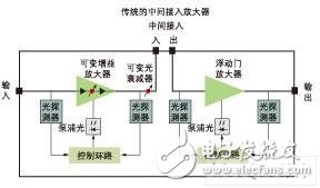
Figure 2. Dispersion-compensating fiber adds some inefficiencies to the design of the mid-stage amplifier.
In principle, two variable gain attenuators can be combined, which greatly simplifies the structure. However, this structure must greatly reduce the optical power of the preamplifier to avoid excessive preamplifier output power (high pump power). Coupled with the large loss of intermediate access, the noise figure of the entire MSA system is significantly reduced.
However, even with two-stage preamplifier, the noise figure of the MSA is limited by another factor: in order to minimize the nonlinear effects produced by the DCF, the input power of the DCF generally needs to be limited to -2 dBm per channel. This requirement further limits the gain of the preamplifier and further affects the noise figure.
If the DCF-DCM is replaced by FBG-DCM, then the low insertion loss independent of the transmission span can make the two variable gain attenuators of the amplifier be combined without affecting the noise figure, and the simplified structure is less. A number of passive optical components (such as optical isolators, pump signal synthesizers, connectors) further reduce the noise figure. Finally, because the intermediate input power is no longer affected by nonlinear effects, the noise figure is further reduced. See Figure 3 for the improvement in noise figure performance obtained as the intermediate insertion loss is reduced. The variable gain region of the MSA in the figure is 10 to 28 dB.
Relationship between noise figure and gain at different intermediate losses
In addition, lower intermediate losses and overall losses, as well as the simplified structure of the amplifier, reduce the total demand for pump optical power. Pump power requirements are reduced and it is possible for the entire MSA to use only one pump source. However, in order to reduce a pump source, some conditions must be met, which leads to intermediate access lag time and transient effect suppression.
Transient effects exist in all optical networks, mainly due to common network operations, such as upper and lower wavelength channels, and unexpected fiber breaks, network rerouting, and reconfiguration can also cause transient effects. Transient effects need to be properly managed to avoid a sudden increase in bit error rate and even damage the receiver in severe cases.
Usually transient effects have rise and fall times, typically on the order of milliseconds, which is usually shorter than the actual reaction time of a standard DCF-DCM. Therefore, to minimize the effects of transient effects, each stage of the amplifier needs to react independently when transient effects enter the stage, so each stage requires separate pump and control loops. .
The reaction time of FBG-DCM is almost non-existent. This feature allows MSA designers to control the entire amplifier using a single control loop.
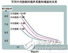
Figure 3. Reducing the intermediate losses can significantly improve the structure of the intermediate access amplifier.
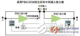
Figure 4. With FBG-DCM, the intermediate access amplifier can be simplified to very few devices and very simple circuits.
Taking the above considerations into consideration, Figure 4 is an optimized MSA for dispersion management using FBG. The advantage of this design is the significantly reduced number of devices (single pump, single variable optical attenuator, reduced detector and passive optical components), and significant circuit simplification (single control loop replaces two discrete control loops) . This will reduce the cost by 30%. Compared to the traditional MSA structure, the number of pins is reduced by 50%. If you integrate the FBG circulator into the amplifier, you can further reduce costs. As shown in Figure 5.
The reduction in pins can significantly reduce system cost, as more devices can now be integrated on a single board. For example, the MSA and FBG-DCM can be integrated on the same line card or the two amplifiers can be integrated in the same package and then mounted on a line card. This is especially useful in ROADM systems because the ROADM system requires the amplifiers to be separated from east to west.
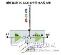
Figure 5 shows a typical ROADM system. One uses FBG-DCM and the other uses DCF-DCM. It can be seen that only two amplifier line cards are required to use FBG-DCM, and four line cards are required to use DCF-DCM.
General architecture strategy
By using FBG-based dispersion compensation, there are several ways to improve the economics of optical transmission in addition to the FBG-DCM optimized MSA discussed above. For a given optical transmission link, how to reduce the cost and topology is related, but there are some simple and intuitive examples that can make the economic improvement immediately emerge.
With low insertion loss characteristics, hundreds of kilometers of single-mode fiber dispersion compensation can be achieved at one node, which greatly improves the economics of the point-to-point network.
Low loss and high allowable power allow network designers to place the compensator directly after the combiner on the transponder side or after the auxiliary amplifier. For DCF-DCM, if the transponder is too close, the loss will be too high, which will limit the dispersion compensation ability. If it is placed directly behind the auxiliary amplifier, it will introduce nonlinear benefits.
For networks that require distributed dispersion compensation, such as the most typical example, when each node requires high signal fidelity, MSA or DCM for the node is usually used. As mentioned earlier, the reduction in the number of MSAs is the most attractive strategy for cost savings in some networks. If this strategy is widely used in the network, the cost associated with the amplifier can be saved by up to 40%.
Even in networks that do not use MSA, the cost savings associated with insertion loss is significant. The light is an amplifier with a small output power, and the cost difference can reach 20% for a standard 80km transmission distance.
FBG-based dispersion management technology provides unprecedented opportunities for network cost and performance optimization in the communications industry. Today, with the issue of cost, especially the cost of future 40G and 100G networks, people's attention has been drawn to this unique and groundbreaking technology. This can be demonstrated by thousands of different types of networks being deployed around the world.
Modular Plug,modular jack rj45,modular jack cat6,mod plugs
NINGBO UONICORE ELECTRONICS CO., LTD , https://www.uniconmelectronics.com