 Coordination of superheterodyne radios Many radio enthusiasts like to install a superheterodyne radio, which has electronic tubes and transistors, but they are often not satisfied after installation and debugging of all levels of work points. The effect of this is probably because there is no good tuning of the radio.
The overall adjustment is through debugging the input circuit of the radio, the local oscillation frequency, and the intermediate frequency correction of the intermediate amplifier circuit, so that the machine has good frequency tracking characteristics within the received frequency range. The so-called tracking refers to that within the frequency range of reception, when receiving a station of any frequency, the local oscillation frequency and the frequency to be received should output a standard intermediate frequency signal after passing through the mixing circuit, in the superheterodyne AM band The intermediate frequency is 465KHZ, and the intermediate frequency in the FM band is 10.5MHZ. Here take the band in the transistor superheterodyne radio as an example to talk about the method of integration.
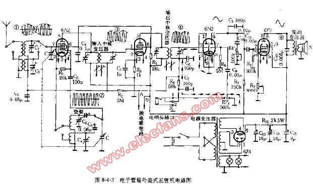
The frequency range of the medium wave is: 530KHZ-1600KHZ, then the frequency range of the local oscillation should be 955KHZ-2065KHZ, the radio changes the resonant frequency of the input loop and the local oscillation at the same time through a double variable capacitor Frequency, under ideal conditions, the difference between the local oscillation frequency and the resonant frequency of the input loop should be kept at 465KHZ in the entire frequency range of the channel when selecting channels, but the actual situation is not so ideal, because the local oscillation circuit It has a different resonant tank circuit and different resonant frequency from the input circuit. Although the resonant capacitors of our input circuit and the local oscillator circuit are synchronously linked, due to the difference in circuit parameters, it is difficult to ensure that within the range of the received frequency Can accurately shoot 465KHZ intermediate frequency, for this reason, some compensation measures have been made in the actual circuit. Figure S is a high-intermediate frequency part of a superheterodyne radio circuit, the local oscillator circuit is mainly composed of B5, C12, C9, dual capacitor C1b, the input loop is mainly composed of L2, C2, C5, dual capacitor C1a. Among them, C2, C5, C9, and C12 are compensation capacitors, C2 and C9 are high-end frequency compensation components, and C5 and C12 are mid-end frequency compensation components. They are all designed to enable the radio to achieve better tracking characteristics. Generally speaking, the coil of the input circuit, the local oscillation coil and the matched double capacitor are all supporting components.
The first step of the tuning is to calibrate the mid-period of the mid-range amplifier so that they all resonate at the frequency of 465KHZ. This step is very important because the input circuit of the radio and the local oscillator circuit are designed with reference to the intermediate frequency. If the IF frequency is not correct, it is difficult to debug the tracking characteristics of the whole machine. It is best to use the 465KHZ signal generator to input the point A in Figure S for the debugging of the central amplifier. Use the DC voltage of the universal meter to measure the voltage at point B (AGC voltage), adjust the magnetic cores of BZ2 and BZ3 to maximize the voltage at point B That's it.
The second step of the tuning is to receive a local strong signal station with a known frequency at the lower end of the band. After receiving the radio sound, see if the frequency indicated by the tuning scale pointer at this time is consistent with the received frequency. If not, You can adjust the magnetic core of the local oscillation coil B5, and turn the tuning knob at the same time until the frequency indicated by the scale pointer is consistent with the received frequency, and then adjust the input loop coil L2 at the position of the magnetic rod until the sound is maximum. If the frequency indicated by the scale pointer is already consistent with the receiving frequency, then just adjust L2 to maximize the sound.
The third step of the tuning is similar to the second step. At the high end of the band, receive a strong signal station with a known frequency. Adjust C2 and C9 respectively so that the frequency indicated by the scale pointer is the same as the received frequency and the sound is maximum. Repeating the second and third steps for fine-tuning is to achieve the best results in reception.
After the high-end and low-end debugging, the mid-end is generally not adjusted, unless you use the wrong component parameters in the input circuit or the local oscillator circuit. Thinking of a simple way to improve the sensitivity of the radio In remote mountainous areas, because the signal field strength is weak, it is difficult for the radio to listen to a clear and stable radio sound. For this reason, it is necessary to find a way to improve the reception sensitivity of the radio. It mainly starts at the mixing level and middle level of the radio.
1. C15 in Figure S is the coupling capacitor of the local oscillator signal coupled to the mixing tube. Properly increasing the capacity of this capacitor can improve the efficiency of the mixing stage.
2. Increasing the working current of the mixing tube by 0.15mA on the original basis can increase the gain of the mixing stage.
3. Reduce the emitter resistance R8 of the first intermediate amplifier, the resistance can be reduced to 60% of the original. Reducing the resistance of this resistor increases the operating point current of this stage on the one hand, and reduces the amount of negative feedback on the other hand, making the gain of this stage greatly improved.
Generally speaking, after the above processing, the sensitivity of the radio will be greatly improved, and the sound will be much brighter. I have handled more than a dozen radios in this way, and the results feel good. Thinking draft

Follow WeChat

Download Audiophile APP

Follow the audiophile class
related suggestion

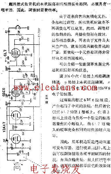
Tracking error measuring device of superheterodyne radio
