The measuring temperature is generally measured by a thermistor. The measuring methods include R-V conversion voltage measurement method and R-F conversion frequency measurement method. The circuits of these two methods are complicated and costly, and many components in the circuit directly affect the measurement accuracy. This paper discusses a kind of R-F conversion frequency measurement method. The NE555 timer and thermistor are used to form the oscillator. The capture function of the MSP430 microcontroller captures the high and low levels of the multivibrator output signal and counts the heat. The resistance Rt is proportional to the difference between the count values ​​when capturing high and low levels.
MSP430 single chip counting method temperature measurement principle
The typical multi-vibrator is composed of NE555 timer. The measured thermistor Rt is connected to the circuit as one of the timing components. The output of the NE555 timer is connected to the P1.2 pin of the MSP430 microcontroller (TImer_A: capture, CCIlA input pin). The system circuit is shown in Figure 3.
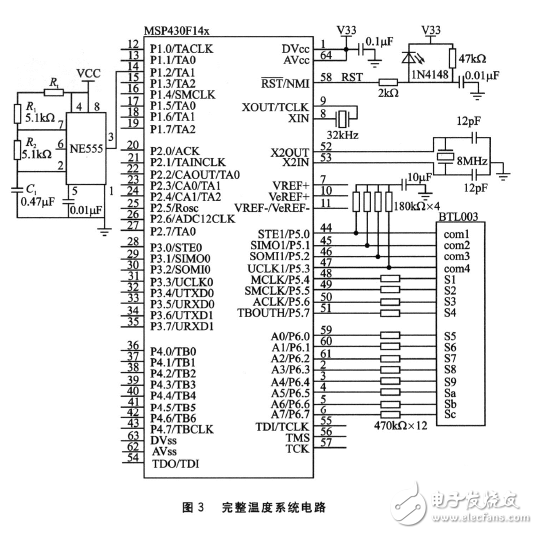
It can be known from the above measurement principle that the main sources of error are: R1, R2 precision, accuracy and stability of the timer and capacitor of the single chip microcomputer. Here, high precision (Shi O.001%) is used, and the temperature coefficient is smaller than that of soil O. 3&TImes; 10-6/°C precision metal foil resistors. Therefore, when a high-precision, high-stability capacitor is selected, and the operating frequency of the single-chip microcomputer is sufficiently high, a good temperature measurement accuracy can be obtained.
It is known from the measurement principle that the larger the resistance of the measured resistance, the smaller the measurement error. I have applied this method to design a thermometer with a measurement range of 10 to 80 ° C and a resolution of O. 01 ° C, the error is in O. Within 3 °C. The design makes full use of the capture function and low-power function of the MSP430 microcontroller, which makes the circuit low in power consumption, simple in circuit, low in price and high in precision.
PCB Connectors: Backplane, Wire-to-Board, Board-to-Board Connectors
These types of connector systems are mounted or processed to a printed circuit board (PCB). There are a variety of PCB connectors and accessories best designed for specific uses. To name some, they include:Din41612 Connector,Board To Board Connectors,battery holders Clips Contacts,Future Bus Connectors,PLCC Connectors.
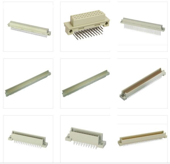
Din41612 Connector
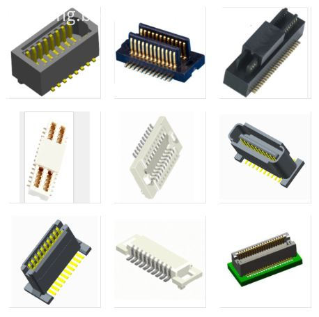
Board To Board Connectors
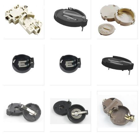
Battery Holders Clips Contacts
Future Bus Connectors
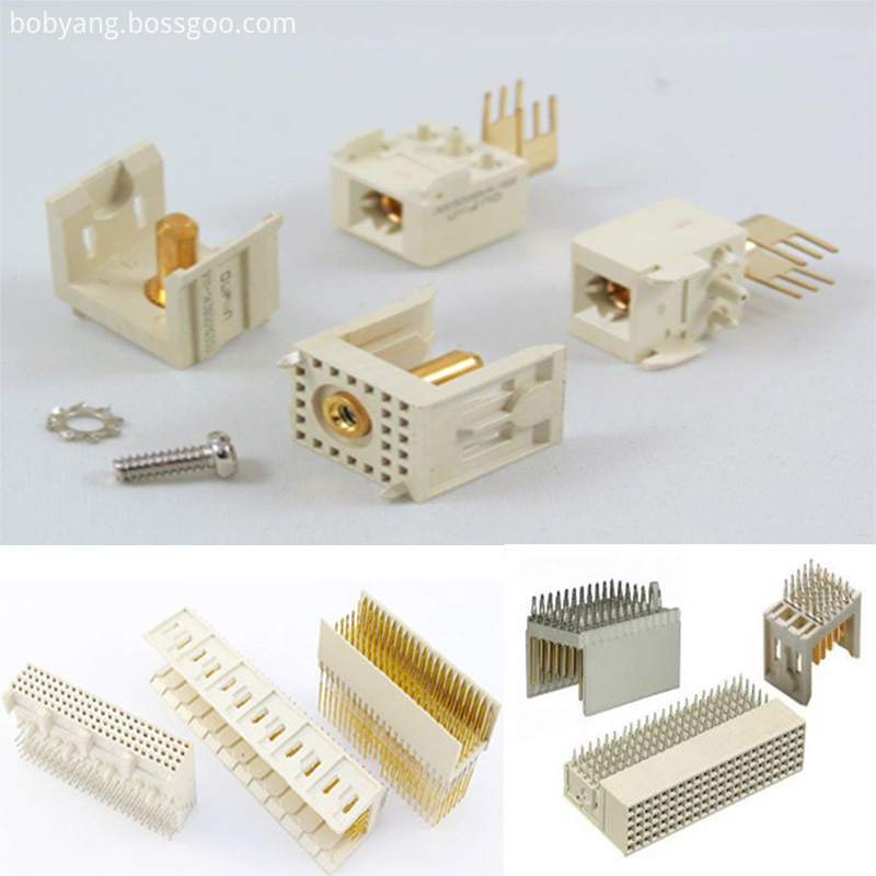
PLCC Connectors
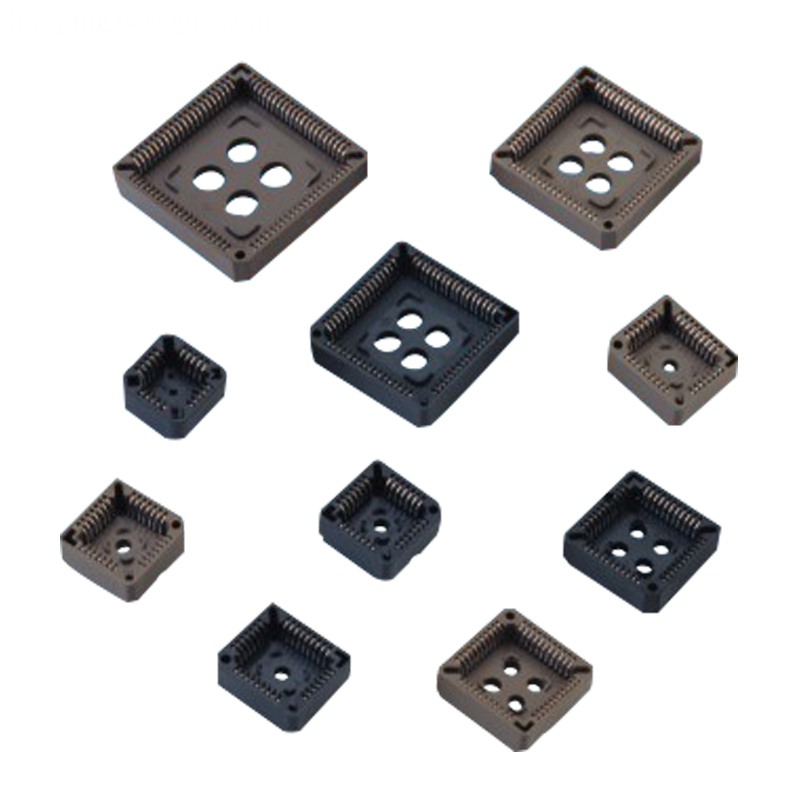
1.ANTENK manufactures a wide range of application specific board stacking PCB connectors which were designed and built to specific customer requirements. Our experienced staff has developed custom products in a variety of contact styles, pitches and stacking heights. Our designs range from new concepts to duplicating existing market products identically or with improvements. Many desigsn are produced using automated manufacturing processes to increase reliability and provide significant cost savings.
2.Our products are widely used in electronic equipments,such as monitors ,electronic instruments,computer motherboards,program-controlled switchboards,LED,digital cameras,MP4 players,a variety of removable storage disks,cordless telephones,walkie-talkies,mobile phones,digital home appliances and electronic toys,high-speed train,aviation,communication station,Military and so on
What is a PCB Connector?
Printed Circuit Board connectors are connection systems mounted on PCBs. Typically PCB Connectors are used to transfer signals or power from one PCB to another, or to or from the PCB from another source in the equipment build. They provide an easy method of Design for Manufacture, as the PCBs are not hard-wired to each other and can be assembled later in a production process.
PCB Connector orientations
The term PCB Connector refers to a basic multipin connection system, typically in a rectangular layout. A mating pair of PCB Connectors will either be for board-to-board or cable-to-board (wire-to-board). The board-to-board layouts can give a range of PCB connection orientations, all based on 90 degree increments:
Parallel or mezzanine – both connectors are vertical orientation;
90 Degree, Right Angle, Motherboard to Daughterboard – one connector is vertical, one horizontal;
180 Degree, Coplanar, Edge-to-Edge – both connectors are horizontal orientation.
Other names for PCB Connectors
PCB Connectors can be known as PCB Interconnect product. Specific terms are also used for the two sides of the connection. Male PCB Connectors are often referred to as Pin Headers, as they are simply rows of pins. Female PCB Connectors can be called Sockets, Receptacles, or even (somewhat confusingly) Header Receptacles.
Din41612 Connector,Board To Board Connectors,Battery Holders Clips Contacts,Future Bus Connectors,PLCC Connectors
ShenZhen Antenk Electronics Co,Ltd , https://www.antenkconn.com