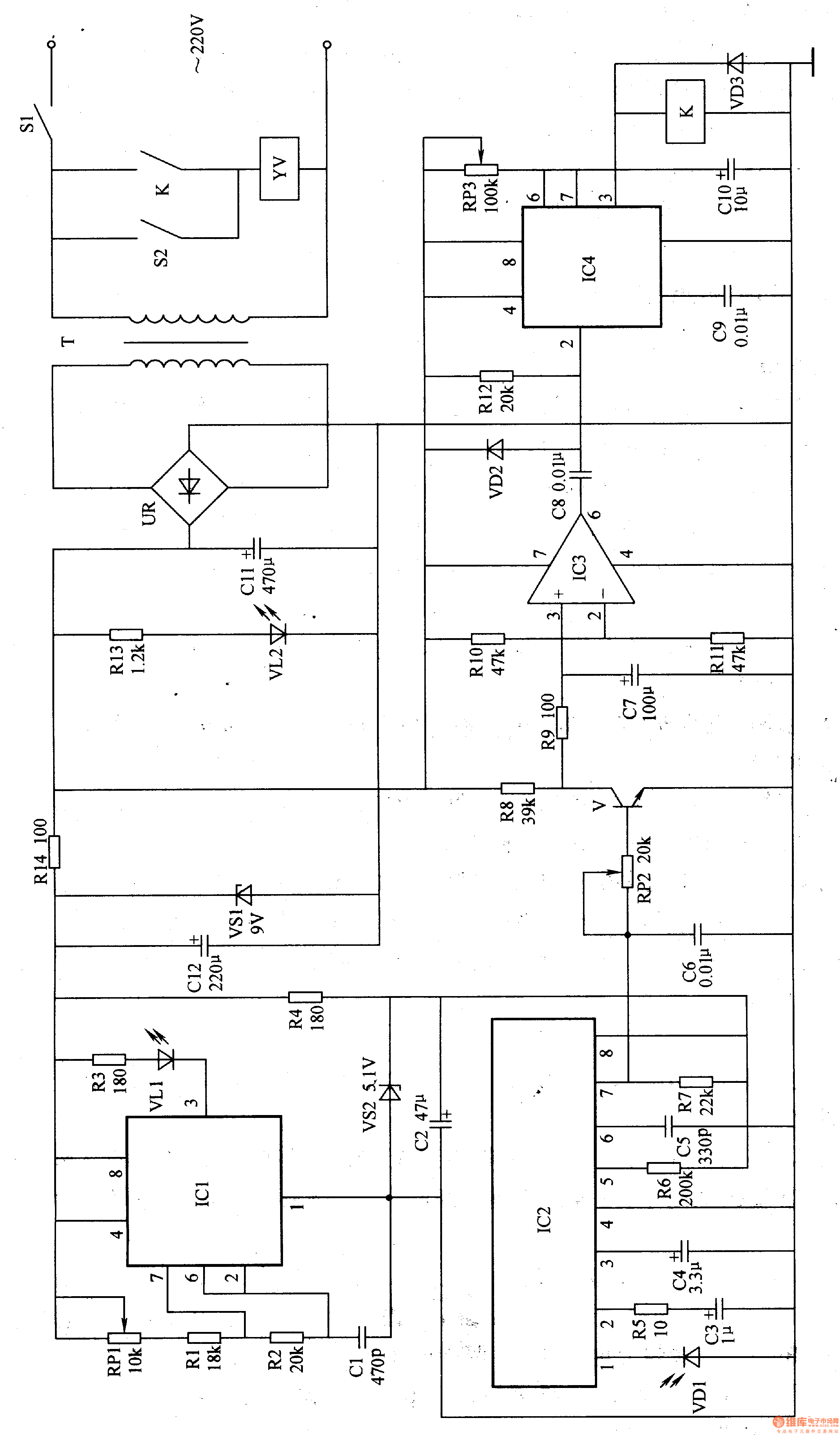
The power circuit is composed of a power switch S1, a power transformer T, a rectifier bridge stack UR, a filter capacitor C2, C11, Cl2, resistors R4, R13, R14, a Zener diode VSl, VS2, and a power indicating LED VL2.
The infrared emitting circuit is composed of an infrared light emitting diode VLl, a resistor Rl-R3, a potentiometer RP1, a capacitor C1 and a time base integrated circuit ICl. lCl and Rl-R3 form a multivibrator.
The infrared receiving processing circuit is composed of an infrared photodiode VD1, a resistor R5-R7, a capacitor C3-C5 and an infrared signal processing integrated circuit IC2.
The delay amplifier circuit is composed of capacitors C6-C8, resistors R8-R11, potentiometer RP2, transistor V, diode VD2 and operational amplifier IC3.
The control execution circuit is composed of a time base integrated circuit 1C4, a resistor R12, a capacitor C9, a ClO, a potentiometer RP3, a relay K, a diode VD3, a manual switch S2, and an electromagnetic water valve YV.
Turn on the power switch S1, AC 220V voltage after T step-down, UR rectification and Cll filter, generate +l2V voltage, one way to supply delay amplifier circuit and control execution circuit; the other way will be V愧 point after R13 current limiting step-down bright.
The +l2V voltage is also subjected to R14 current limit, VSI voltage regulation and CI2 filtering to generate +9V voltage, one channel is directly supplied to the infrared transmitting circuit; the other channel is also subjected to R4 current limiting, VS2 secondary voltage regulation and C2 filtering to generate +5V voltage. As the operating voltage of the infrared receiving processing circuit.
After the infrared transmitting circuit is energized, a pulse signal with a frequency of 38-4OkHz is output from the 3 pin of IC1, and VL1 is driven to emit modulated infrared light.
Usually (when no one is in the bathroom), VDl can not receive the infrared light emitted by VL, IC2's 7-pin output is high, V-saturation is on, IC3 is low, IC4's 2 is high, 3 feet The output is low, K is in the release state, and YV is not working.
When someone enters the bathroom, the infrared light emitted by VLl is reflected back by the human body. VDl receives the infrared light reflected by the human body and converts it into an electrical signal. The electrical signal is processed by the circuit in IC2 and output from the 7th pin of IC2. Low level, V cutoff, C7 is slowly charged via Rg and R8. When the voltage across C7 exceeds the voltage of pin 2 of IC3, IC3 outputs a high level. After the high level of this transition is processed by C8 and VD2, Rl2, a positive pulse is generated at the 2 pin of IC4, and the circuit in IC4 cannot be triggered. , 3 feet still output low level.
When the person leaves the bathroom, VD1 can not receive the infrared light signal, IC7's 7 pin becomes high level, V saturation turns on, C7 is quickly discharged through R9 and V, IC3's 6 pin outputs low level, this low level After C8, VD2 and Rl2 processing, a low-level trigger pulse is generated, so that the circuit in IC4 is triggered to be flipped (from steady state to transient state), 3 feet are changed from low level to high level, and K is energized and pulled. The normally open contact is turned on, and the YV is energized to start discharging water.
While the 3 pin of lC4 outputs a high level, C10 is quickly discharged by the 7-pin internal circuit of 1C4, and then slowly charged by RP3. When the voltage across C10 is charged to 8V or more, the circuit in IC4 is turned over and returned to steady state. The 3 pin outputs low level, K is released, and YV is powered off to stop discharging.
Adjusting the resistance of RP1 can change the oscillation frequency of the multivibrator.
Adjusting the resistance of RP2 can change the sensitivity of V conduction.
Adjusting the resistance of RP3 can change the time that YV delays energization.
Component selection
Rl-Rl4 uses 1/4W metal film resistor or carbon film resistor.
RPl-RP3 uses ultra-small synthetic carbon film potentiometer or variable resistor.
Cl and C5 use high frequency ceramic capacitors or glass glaze capacitors; C2-C4, C7, ClO-Cl2 select aluminum electrolytic capacitors with a withstand voltage of l6V; C6, C8 and C9 use monolithic capacitors or polyester capacitors.
VDl selects PH302 type infrared photodiode; VD2 and VD3 select 1N4001 type silicon rectifier diode.
VLl selects SE303 type infrared light emitting diode; VL2 selects p3mm high brightness light emitting diode.
VSl selects silicon steady voltage diode of lW and gV; VS2 selects silicon steady voltage diode of 1/2W and 5.lV.
UR uses 1-2A, 5OV rectifier bridge stack.
Both ICl and lC4 use NE555 type time base integrated circuit; IC2 selects CX2O106A or KA2184 type infrared signal processing integrated circuit for IC2; IC3 selects LM741 or μA741 type operational amplifier integrated circuit for IC3.
T selects 5W, the secondary voltage is 10-12V power transformer.
YV selects AC 220V electromagnetic water valve.
Modern Physics Experiment Series
Modern physics experiment related equipment for efficient specialized physics laboratory
Modern Physics Experiment Instruments,Optical Instruments,Acousto-Optic Modulator Experimental Device,Optical Spectroscopy Experiment Determinator
Yuheng Optics Co., Ltd.(Changchun) , https://www.yuhengcoder.com