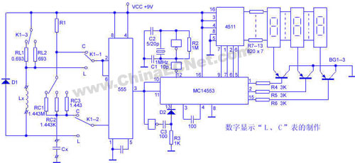
When electronic enthusiasts make balanced capacitors and speaker crossover inductors, a slight error will damage the sound quality. Here to introduce a simple production of L, C table, the circuit digital display, intuitive, convenient, high precision.

First, the principle
1. Parameter conversion circuit:
The parameter conversion circuit is composed of a 555 time base to form a multivibrator, and the device under test Lx/Cx can be converted into a pulse width proportional to the component parameters. The rectangle with the specific pulse width is then used as the gating signal, and the pulse width (actually the component parameter) can be displayed through the display by counting the standard pulse of a known period within the pulse width time.
When measuring the capacitance (the band switch is at 5, 6, and 7 bits), the multi-vibrator is a Cx timing component. The generated rectangular wave is output through the 3-pin and sent to the gate of the counter. The pulse width is tw=CRcln2. .
When measuring inductance (band switch is 1, 2, 3 bits), it is a multi-vibrator with Lx as the timing component. When the power is turned on, V2(6)=Vcc, 555's 3 pin outputs low level, 7 The ground is connected to the ground, and the power supply is charged by the Lx of the RL. As the charging progresses, V2(6)↓, when V2(6)=1/3Vcc is reached, the circuit is turned over, the 3 pin outputs a high level, and the 7 feet and the ground are broken. On, because the Lx current can not be abrupt, it will produce an induced electromotive force to make D1 turn on, Lx discharge through D1, RL, V2(6)↑, when V2(6)=2/3Vcc is reached, the circuit flips again, 5 The pin outputs a low level, the 7 pin is connected to the ground again, and the Lx starts to charge again, so that the 5-pin output square wave with a duty ratio of 1:1 is sent to the gate of the counter. At this time, the pulse width is tw=Lx/RLln2.
2. Standard pulse generator:
The circuit consists of inverters 3, 4 and a crystal with a crystal frequency of 1 MHz and a standard pulse period of T = 1 μs as the count pulse of the counter.
3, counting, display circuit:
The display consists of three LED digital tubes, and the counter is composed of MC14553 three-bit dynamic scanning counter. The standard pulse of T=1μs is sent to the 12th pin of the MC14553. The rectangular pulse generated by the multivibrator is sent to the 11th pin of the MC14553. When the 11 pin is high, the 12-pin standard pulse of the 4553 cannot be added, and the 11 pin is low. Usually, after inversion and differentiation, a positive pulse is obtained, and the counter is first cleared. At the same time, the 4553 latch is released, and the standard pulse is counted. When the 11 pin is input to the high level, the counter is latched again. The pin is also high level, the data of the counter is latched, the display is stable display of the previous counting result, and the counter is set to N in this cycle, then tw=NT, that is, Lx/RLln2=NT, reasonably select RL or Rc, The display can display the Lx micro-five number or the Cx skin method. It is very intuitive. The instrument Lx has 0~999μH and 0-999mH. Cx has 0~999pF, 0~999nF (nano), 0~999μF. Third gear.
Second, the production points
The key components are the range resistors RL and Rc. The 0.693 Ω and 1.443 Ω resistors can be wound by high-strength enameled wire, preferably on the bridge to ensure 1% accuracy. Other range resistors can be obtained by connecting multiple resistors in parallel, and should also guarantee 1% accuracy.
Third, debugging
The adjustment of this circuit is extremely simple, just adjust C2 so that the standard pulse frequency is 1MHz, and it is not necessary to zero after use.
Although this circuit uses only a 3-digit digital tube for display, it can display six significant digits. If there is a 47312pF capacitor, only 732pF is displayed in the pF file. After dialing the nF file, the display shows 004nF, so the measured capacitance is 004732pF, which is 4.732nF, which is 0.04732μF. The same is true for inductance measurement. Extremely convenient.
LED digital tube
The LED digital tube is a lighting decoration and lighting fixture that uses a light-emitting diode as a light-emitting unit.
R&M BOX PRO 6000 Puff is a Disposable Vape Ecig with colorful RGB light and it is rechargable. It contains 10mL of e-liquid and vape up to 6000 puffs. There are 10 flavors for you to choose. RGB lights make it the coolest Disposable Electronic Cigarettes, and a rechargeable USB port on the bottom of the device ensures you use up every drop of e-juice in the can and keep it lit all the time.
1. Newest technology mesh coil with 1.0Ω, smoother and bigger vapor, create the purest taste.
2. Integrated 850mAh A grade Rechargeable battery, don't need to worry battery run out soon .
3. Refillable and equipped 10ml imported E-liquid, fill it at any time and keep e liquid fresh. And you can fill more e liquid if 10ml use out.
4. Implanted 6 colors RGB light on the oil tank, sparkling atmosphere, let the vape no be alone.
5. Unique MOD molding with visual oil tank, classic box mod shape, Cheap price but enjoy a luxury feeling.
Better than better. R&M BOX PRO, your new generation vape device.
If you like Huge vapor, can find the product similar like Fluum Bar 6000 puff,R&M Monster 7000 hit,R&M LEGEND 10000 Puff.R&M 1000 Puffs also good taste.
Disposable E-Cigarette,Vape Box,Vape Mod,R&M BOX PRO
Shenzhen Essenvape Technology Co., Ltd. , https://www.essenvape.com