A single-chip MPEG-2 decoding scheme for DVB-C
In the 21st century, the development of digital TV in the world is quite rapid, DVB video broadcasting in Europe is quite mature, Japan and the United States have also begun to broadcast high-definition programs, and set the time for digital TV broadcasting to completely replace analog TV broadcasting. table. In China, DVB-S has formed a relatively mature market because more than 30 sets of programs in various provinces and cities have been compressed by MPEG-2 and transmitted via satellite. At present, there are many domestic manufacturers independently developing DVB decoder sets, producing and selling DVB-S, and the price has dropped to a level that users can afford. In contrast, DVB-C, there are also many manufacturers to launch prototypes, but because the function can not fully meet the needs of TV stations and users and the source-side equipment transformation requires a long process, there has not yet formed an obvious market.
At present, in addition to completing the basic audio and video decoding, DVB-C must add the following functions to be truly accepted by the market. First, provide support for CA (Conditional Access) systems. The cable television station needs to realize the encryption of the program and the management and charging of users through the CA system. CA system requires that at the receiving end, the set-top box should support IC-Card interface to communicate with SmartCard, and provide a standard DVB data stream descrambling module. Second, realize the storage of TS stream. There are two trends in this function: one is that the set-top box provides a hard disk interface (such as an IDE interface), and the TS stream is stored in the hard disk for user playback to realize the function of a digital recorder; the other is that the set-top box provides USB or 1394. The high-speed general-purpose interface stores TS streams through them into the computer, and the user then processes them through the computer. Third, realize the LAN network interface. In this way, the set-top box can receive the TS stream from the local area network and realize the video playback on the local area network. Fourth, realize the Web browsing function. Users can browse the web through the set-top box, of course, this requires the appropriate improvement of the existing TV resolution and the provision of specialized websites.
In response to these requirements of DVB-C set-top boxes, Fujitsu's single-chip MPEG-2 decoding scheme was selected. This set of schemes supports various interfaces and functional modules better, and the cost is lower. The following is a brief introduction to the chip The software and hardware of the entire package.
1 Chip introduction
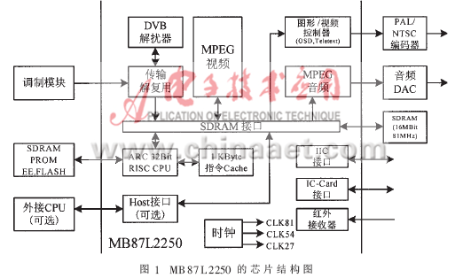
MB87L2250 is a single-chip MPEG audio and video decoder produced by Fujitsu. It also has a demultiplexing function and integrates a 32-bit RISC processor. It provides a cost-effective and highly integrated solution for digital TV set-top boxes. In the chip design, MPEG decoding and demultiplexing are all done by hardware, while the on-chip integrated processor with a working frequency of 54MHz is mainly used to run customer applications, such as implementing a graphical interface. Because MB87L2250 uses a 2.5-frame architecture, only 16M-bit SDRAM is needed for MPEG decoding, OSD menu, and data cache. The entire chip has the following characteristics:
· 32-bit RISC microprocessor · 1K byte instruction cache
· 2.5 frame architecture · Only need 16M SDRAM
· Support 32 different PID packages · Hardware filters for PID and SecTIon
· Infrared receiver · DVB standard descrambling
· Reducing the picture memory · The VBI mode of teletext is inserted into the memory saving mode
· 16: 9 and 4: 3 format conversion · Movie format conversion
· IIC bus · Two SmartCard interfaces
· 2, 4, 6 or 8 bit OSD · 16 programmable I / O ports
· Automatic clock recovery
Figure 1 is a chip structure diagram of MB87L2250.

1.1 32-bit RISC processor
The on-chip integrated ARC processor is a RISC microprocessor using 4-layer pipeline technology, and its operating frequency is 54MHz. ARC internally integrates a 256 × 32-bit instruction cache. ARC's storage controller includes SRAM and SDRAM controllers. The SRAM controller includes a programmable wait state generator to synchronize with the connected storage media of different rates. The MPEG decoder is located in the auxiliary address space, and can access all ARC registers and the entire address space of the processor through a host interface. This feature is mainly used for debugging, but can also be used for the first start based on FLASH system. The chip also has a sleep state, at this time the working frequency of ARC is 13.5MHz.
1.2 Transport stream demultiplexing and system decoding
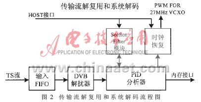
It is the transmission system decoder (TSD) that performs this part of the function. Through TSD, the main chip can receive 8-bit parallel or serial data streams. TSD provides basic synchronization and error detection functions, but its main function is to act as a PID analyzer to identify the only PES stream from the maximum 32 PES streams in the TS stream. TSD selects the corresponding valid data and system information and sends them to the decoding buffer. In addition, TSD also provides analysis and comparison of segmented (SecTIon) type data.
TSD mainly includes channel decoder (Channel Decoder), PCR storage (Program Clock Reference Store), PID analyzer (PID parsing engine), segmented data filter (SecTIon Filter) and so on. In order to support CA systems in cable broadcasting, TSD also includes a standard DVB descrambler. This descrambler can descramble in TS layer and PES layer, can process eight different streams in parallel, so it needs to store eight pairs of control words. The descrambler can automatically find the corresponding control word. The flow chart of transport stream demultiplexing and system decoding is shown in Figure 2.

1.3 Video decoding and output
The entire video decoding and video display process is managed and monitored by VD_VUM (Video Unit Management). Below it is mainly divided into three parts. Among them, the memory allocation of video decoding and reference image is managed by VUM_VDM (Video Decoder Manager); the image display is controlled by VUM_VOM (Video Output Manager); the cache management of B-frame image is managed by VUM_MIM (Memory Interface Management).
Video output is mainly completed by the video output interface. The video output interface reads the decompressed video data from the local SDRAM and outputs it in Y, Cb, Cr format. It also provides digital video output, which is designed to be directly connected to the video DAC. This module also includes a special hardware module to support OSD (OnScreenDisplay) and insert teletext in VBI mode. The video output interface also includes line and field synchronization filters to support some video format conversion, including chrominance signal conversion and high-definition format conversion.
1.4 Various interfaces
MB87L2250 supports many interfaces. In addition to the general Debug port and serial port, it also supports IC-Card interface and a Host interface. The IC-Card interface provides two independent interfaces that support ISO 7816 IC-Card. They only support asynchronous IC-Card. This interface is directly controlled by the main interface of the CPU, so it will not affect the audio and video decoding. At a certain moment, only one interface can be activated, and the other keeps its last state. This interface mainly includes a serial-to-parallel and parallel-to-serial converter, which requires the support of clock and logic control. The CPU provides the complete data frame to be transmitted to the IC-Card, and receives all the data frames from the IC-Card. The IC-Card interface monitors the interface clock and supports data frames, data clocks, and error handling, while the CPU is responsible for packaging communication protocols and frames. The Host interface is used to connect other CPUs without using the integrated ARC processor. It can also be used to expand RAM or external hard drives. It supports three kinds of CPU: FR30 (max 25MHz), Motorola68xxx (max 33MHz), SPARClite series (max 40MHz).
2 Introduction
2.1 System schematic diagram and introduction of peripheral chips
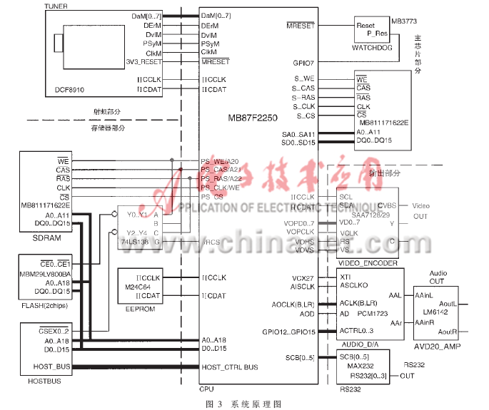
The whole system is composed of four parts: radio frequency, main chip, memory and output. The following will introduce the other three parts except the main chip part. Figure 3 is a schematic diagram of the system principle.

(1) RF part
The radio frequency part mainly includes a high-frequency head and a demodulation chip, respectively performing frequency conversion and channel decoding of the radio frequency. The high-frequency head selected in this system is the DCF8910 from THOMSON, and the demodulation chip is STV0297 from ST. When the system is working, the digital modulation signal in the RF frequency band is down-converted by the high-frequency head, and then quadrature demodulated into two IQ signals. Then input the digital baseband signal into STV0297, perform digital-to-analog conversion and channel decoding to form a digital signal to the subsequent stage, including DaM [0..7], error signal DErM, data valid DvLM, frame synchronization PsyM, clock signal ClkM. Read and write operations to the high-frequency head and STV0297 are completed through the IIC bus.
(2) Memory section
The memory part includes two 512K × 16Bit FLASH, one 2 × 512K × 16Bit SDRAM, one 64Kbit EEPROM and one IDE hard disk hanging on the Host interface. Two pieces of FLASH are used to store data that generally do not need to be changed. One piece is for starting FLASH, which is used to store application programs of the system; the other piece is user FLASH, which is used for storing larger bitmaps. SDRAM is used as the memory space when the application is running. Its address lines include row selection address lines a0 ... a11, column selection address lines a0 ... a7 and Bank selection line a11. The total address space is 2M bytes. FLASH and SDRAM share a data bus and an address bus. To avoid conflicts, a 74LS138 decoder is needed for chip selection. EEPROM chooses 24C64, read and write it through serial IIC bus.
(3) Output section
The output part consists of audio output, video output and serial output. The video part uses the video encoding chip SAA7128 / 29, which converts the digital video format sent out to digital-analog conversion and encodes it into an analog video signal through the video matrix. It can output cvbs, y, c and R, G, B three signals. The chip works in Slave mode, that is, the data clock is supplied by the main chip. SAA7128 / 29 uses this clock to latch digital signals. The control signals include Hs line synchronization and Vs field synchronization, and the main chip controls it through the IIC bus.
The audio part uses PCM1723 to perform digital-to-analog conversion on the PCM digital audio sent from the main chip. Its clock includes left and right clocks and bit clock. PCM1723 is synchronized by the 27MHz signal generated by the main chip: it uses the oversampling clock obtained by dividing the 27MHz signal to latch the digital signal, and at the same time sends the oversampling clock back to the audio output part of the main chip for synchronization, Therefore, the output of the audio digital signal is synchronized with its latch. After the digital-to-analog conversion of the audio, it can be sent to the vocal part through analog amplification (such as LM6142).
2.2 Introduction to software modules and functions
In order to enrich the functions of the DVB-C set-top box, in addition to audio and video decoding and control and basic DVB-C functions, the following software modules have been written:
(1) GUI (Graphic User Interface) based on embedded system.
The beautiful, concise and powerful graphical interface is very important for DVB-C set-top boxes, so a GUI based on embedded system was written. In this system, the GUI mainly completes three parts of functions: First, encapsulates the graphic design API. The basic graphics primitives have been implemented in the OSD driver, including basic operations such as dots, lines, rectangles, and filling, and the storage and display of Chinese character fonts. But in order to adapt to the call of the application layer, these primitives must be packaged into API in the GUI; second, provide a graphical control (Control) mechanism. The concept of graphical control in Windows9x is in line with the idea of ​​object-oriented programming, it is simple and flexible to use, and it is also very convenient to maintain and modify. In the design of GUI, the control mechanism is implemented in the light of Windows9x; thirdly, the management of inter-process communication and message passing. In a multi-process real-time system, the GUI must also contain a process to receive messages sent by other processes to the user interface.
(2) File system on EEPROM
User information is mainly stored in EEPROM. With the continuous enrichment of functions, users will have more and more information to store, so a simple and effective file system is needed to organize various information. At the same time, the file system should also try to overcome the shortcomings of long EEPROM read and write time, power off when read and write is not allowed. This file system mainly completes three parts of functions: first, establish a file directory mechanism that is basically the same as popular operating systems. Specify 32 bytes as a file block (BLOCK), a file is composed of one or more file blocks. The files are organized in a tree structure, and the files at the same level are connected by a doubly linked list mechanism. When writing information, the pointers will not be operated, which ensures security; second, the design of EEPROM read and write timing and strategies. Each time when starting up, an area of ​​the same size as the EEPROM is opened in the SDRAM as a mirror image. All read operations are performed in the image, which will greatly improve the efficiency of the read operation, and the write operation will operate on the EEPROM and the image at the same time to ensure that the information in the image and the EEPROM is completely consistent; third, provide powerful power-off protection. Before writing to the EEPROM, first record the operation process that needs to be performed and clear the operation completion flag; if the power is interrupted during the operation process, the next time the power is turned on, according to the operation completion flag, it can be known that the EEPROM has been powered off during the operation process , Follow the recorded operation process to resume operation.
Ac Three Phase Generator,Rainproof Diesel Generator,Open Type Diesel Generator,Rainproof Diesel Generator Set
Jiangsu Lingyu Generator CO.,LTD , https://www.lygenset.com