More and more wearable devices and IoT designs see the ability to detect direction and track motion as an important requirement. Although there are a variety of motion sensors available, engineers continue to be challenged to explore these devices faster and more efficiently with lower power consumption, which is especially challenging when adding additional sensors.
To address these motion tracking challenges, designers need more integrated accelerometers, gyroscopes, and magnetometer hardware, as well as more efficient and intelligent data fusion algorithms.
This article describes the solutions provided by TDK InvenSense that help both hardware and software. Then, this article will show you how designers can begin to apply this solution to simplify the development of complex low-power multi-sensor applications that require complex motion sensing capabilities.
Efficient motion tracking challengesWith traditional motion tracking methods, developers can handle important integration issues for both hardware and software. On the hardware side, developers often try to minimize the complexity, size, and number of parts in designs built with separate sensors, including accelerometers, gyroscopes, and magnetometers. Software engineers need to pay special attention to synchronizing the various sensor outputs to create the unified data flow required by the sensor fusion algorithms used in advanced motion tracking applications. For hardware and software developers, the challenges of applications that require additional sensor types in their designs are significantly increased.
However, with the TDK InvenSense ICM-20948, developers can quickly implement motion tracking designs or other multi-sensor systems with minimal effort.
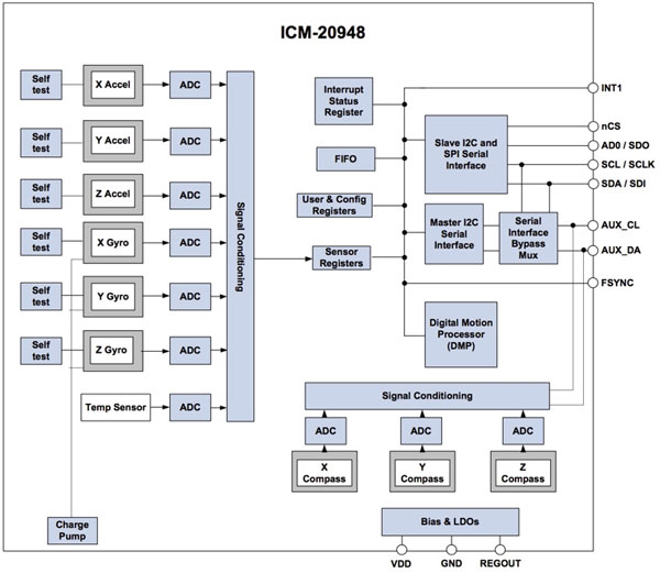
Motion tracking solutionThe TDK InvenSense ICM-20948 is a multi-chip module measuring only 3 mm x 3 mm x 1 mm. It integrates the complete sensor, signal chain, data processing and interface circuitry required to provide a complete motion tracking solution (Figure 1). .

Figure 1: The TDK InvenSense ICM-20948 performs motion tracking through its dedicated signal chain, programmable filters, interface circuitry, and digital motion processor. (Source: TDK InvenSense)
The module requires only about 3 milliamps (mA) in full operation to achieve its full functionality. For power-constrained applications, developers can turn off certain parts of the module, reducing the current consumption of each stage in full-sleep mode to 8 microamps (μA). The resulting power dissipation is dependent on the operating voltage (VDD), which can be between 1.71 volts and 3.6 volts, depending on the design requirements.
A separate signal chain is integrated into the module to support each channel of the integrated 3-axis accelerometer, 3-axis gyroscope and 3-axis magnetometer as well as an integrated temperature sensor. Each signal chain includes a buffer amplifier and a dedicated 16-bit analog-to-digital converter (ADC), as well as sensor-specific circuitry such as the current source of the Hall-effect magnetometer that drives the module.
To increase the output of each signal chain, the module includes a signal conditioning stage that is appropriate for each further sensor type. For example, the magnetometer output performs basic signal processing through an arithmetic circuit, while the outputs of other sensors are each fed into an automatic sensor-specific adjustment phase to perform processing functions such as sample averaging. Developers can set the ICM-20948 to average up to 128 gyroscope data samples, or set the accelerometer to an average of up to 32 samples. Finally, the output of the signal conditioning stage of each channel is fed into a dedicated set of sensor registers.
At the heart of the ICM-20948 is a proprietary digital motion processor (DMP) that provides a variety of functions, including motion processing algorithms, calibration, and self-testing. During normal operation, DMP processes data from dedicated sensor registers. The result is then stored in the module's integrated FIFO for the host MCU to access via a shared I2C or SPI bus.
The functionality of DMP and FIFO provides important functionality for many practical applications. In many cases, applications update their motion tracking results at a relatively slow rate, even allowing their host processors to sleep between updates to reduce overall power consumption. However, the motion tracking algorithm requires significantly faster updates to ensure that it provides accurate data with the lowest latency when the application requests an update. DMP maintains high update speeds without the need for host involvement, which helps ensure accuracy without imposing additional requirements on the performance or power consumption of the host application itself.
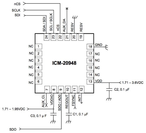
Simple integrationCombining small package, system integration and host independent operation, the ICM-20948 is ideal for use in mobile devices, wearable devices and IoT designs. The high level of integration of the module means that developers can perform typical motion tracking designs using only three capacitors. Following the recommendation of TDK InvenSense to use ceramic X7R parts, the developer will add a 0.1 μF capacitor to the REGOUT pin of the module for voltage regulator filtering and add a capacitor to its VDD and VDDIO pins for power supply bypass ( figure 2).

Figure 2: Designers can easily add the TDK InvenSense ICM-20948 to an MCU-based design to connect to the MCU via SPI (shown here) or the I2C interface, which uses the same configuration but pin 22 (nCS ) Associated with VDDIO. (Source: TDK InvenSense)
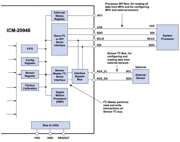
While the ICM-20948 provides a nearly direct replacement solution for motion tracking design, many applications place demands on other sensor types. To help developers simplify these multi-sensor designs, the ICM-20948 provides a separate I2C interface and built-in support for other external sensors. Here, the developer connects the I2C-compatible smart sensor to the module's dedicated auxiliary I2C port (Figure 3).

Figure 3: While the SPI (or I2C) is connected to the host MCU, developers can use the auxiliary I2C interfaces (AUX_CL and AUX_DA) of the TDK InvenSense ICM-20948 module to connect external sensors and manage them through the ICM-20948's auxiliary device-specific registers. they. (Source: TDK InvenSense)
In normal operation, the ICM-20948 will act as an I2C bus controller to communicate with external sensors. In this mode, the developer can program a set of dedicated module registers to define the I2C address, output data address, and other transmission parameters of the external device. With this information, the module can read external sensor data into its FIFO and external device data registers, using single-byte or multi-byte reads on the sensor I2C bus without involving the host MCU.
The ICM-20948 provides an additional feature specifically designed to coordinate the time between the ICM-20948 and external sensors. In addition to using the module's dedicated interrupt INT pin, developers can use the external sensor's interrupt or sync pulse to drive the module's FSYNC pin. For example, in image stabilization applications, developers can use the image sensor's frame sync output to synchronize image data with the ICM-20948 sensor readings. Using the module's FSYNC_CONFIG register, developers can even configure the module to measure the time between the external sensor FSYNC event and the ICM-20948 data event, providing more dense synchronization between image and motion data.
However, as a dedicated motion tracking device, the ICM-20948 lacks the functionality required to configure external sensors using device-specific setup operations that are typically handled by the host MCU. To simplify the system initialization process, the module provides a pass-through mode to connect the host system processor directly to an external sensor using an integrated interface bypass multiplexer.
In pass-through mode, the device uses its integrated analog switch to electrically connect the auxiliary I2C pins AUX_CL (pin 7) and AUX_DA (pin 21) directly to the host I2C bus (pins 23 and 24). This mode of operation provides an easy way to allow the host processor to handle any configuration and setup requirements associated with each external sensor. After initialization, the developer disables the bypass multiplexer to allow the ICM-20948 to take over external sensor access during normal operation.
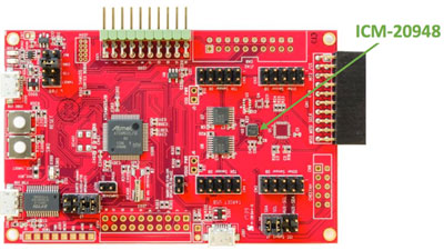
Rapid developmentAlthough ICM-20948 proposes relatively simple interface requirements, developers who wish to evaluate motion tracking solutions can even avoid this level of hardware prototyping. TDK InvenSense's DK-20948 evaluation board and reference design provide an off-the-shelf development platform that combines a host MCU, embedded debugger, USB interface and multiple connectors, wireless connectivity and other features for adding additional sensors (Figure 4 ).

Figure 4: The TDK InvenSense DK-20948 board provides a complete motion-sensing design that combines the ICM-20948 module with the Microchip Technology ATSAMG55J19B MCU (middle left) and the Microchip AT32UC3A4256 MCU (located on the back side of the board) Debugger. (Source: TDK InvenSense)
Based on the Microchip Technology ATSAMG55J19B MCU, the DK-20948 board provides a complete motion sensor design using the ICM-20948. At the same time, the board includes a Microchip AT32UC3A4256 MCU with embedded debug capability to eliminate the need for external tools when used in conjunction with the host ATSAMG55 MCU. Developers can use the board to evaluate the ICM-20948, during which no further hardware work or other custom or available daughter boards are available to extend its functionality. Once the developer has completed their ICM-20948 evaluation, they can create a custom design using the kit's schematic, detailed BOM and board design files.
For software engineers, the DK-20948 kit also includes options for rapid evaluation and custom development. For evaluation, the company's MoTIonLink GUI-based tools allow developers to explore different configuration settings and evaluate their impact on the resulting motion data. However, for most developers, the suite's software development kits will soon become their primary focus.
Custom softwareFor custom software development, the TDK InvenSense eMD (Embedded Motion Drive) SmartMoTIon package provides application programming interface (API) documentation, driver source code, sensor fusion libraries, and pre-built DMP firmware images. The package also includes tools for building and flashing custom firmware images and command line utilities for interacting with the EV kit.
The eMD software platform is designed to work with Atmel/Microchip Technology Atmel Studio and includes two Atmel Studio packages: the core and the application. The kernel package contains the underlying drivers and firmware required to program and operate the ICM-20948, as well as the pre-built motion algorithms and math files for the Microchip ATSAMG55J19B host MCU on the DK-20948 board.
The application package includes a sample application that demonstrates the use of the kernel package, including the main design patterns that extend from the top-level application to the serial bus transaction. For example, the main C routine shows how developers can initialize ICM-20948 and get data (Listing 1).
Int main (void)
{
...
/* IniTIalize icm20948 serif structure */
Struct inv_icm20948_serif icm20948_serif;
Icm20948_serif.context = 0; /* no need */
Icm20948_serif.read_reg = idd_io_hal_read_reg;
Icm20948_serif.write_reg = idd_io_hal_write_reg;
Icm20948_serif.max_read = 1024*16; /* max num bytes allowed per serial read */
Icm20948_serif.max_write = 1024*16; /* max num bytes allowed per serial write */
Icm20948_serif.is_spi = interface_is_SPI();
...
* Setup the icm20948 device */
Icm20948_sensor_setup();
/*
* Now that Icm20948 device was iniTIalized, proceed with DMP image loading
* This step is mandatory as DMP image are not store in non volatile memory
*/
Load_dmp3();
/*
* Initialize Dynamic protocol stuff
*/
DynProTransportUart_init(&transport, iddwrapper_transport_event_cb, 0);
DynProtocol_init(&protocol, iddwrapper_protocol_event_cb, 0);
/*
* Initializes the default sensor ODR in order to properly init the algorithms
*/
Sensor_configure_odr(period_us);
InvScheduler_init(&scheduler);
...
While (1) {
InvScheduler_dispatchTasks(&scheduler);
If (irq_from_device == 1) {
Inv_icm20948_poll_sensor(&icm_device, (void *)0, build_sensor_event_data);
__disable_irq();
Irq_from_device = 0;
__enable_irq();
}
}
Return 0;
}
Listing 1: Developers can check the sample source code provided in the DK-20948 eMD SmartMotion package for the main design patterns, such as the ICM-20948 initialization and sensor wheel listed in this code snippet in the main.c routine of the sample application. Inquiry mode. (Source: TDK InvenSense)
When programming highly integrated devices such as the ICM-20948, developers can easily find that they not only have to deal with many of the device's configuration options, but also the large number of software components required to efficiently operate the device. The eMD kernel package eliminates this complexity through a series of abstractions, including software architecture and service layers. For example, the key software structure inv_icm20948 collects all the data and metadata needed to operate ICM-20948, including its serial interface definition (Listing 2).
/** @brief ICM20948 serial interface
*/
Struct inv_icm20948_serif {
Void * context;
Int (*read_reg)(void * context, uint8_t reg, uint8_t * buf, uint32_t len);
Int (*write_reg)(void * context, uint8_t reg, const uint8_t * buf, uint32_t len);
Uint32_t max_read;
Uint32_t max_write;
Inv_bool_t is_spi;
};
Listing 2: To help reduce software complexity, the DK-20948 eMD SmartMotion software kernel routine provides a number of C language constructs, an example of which defines the ICM-20948 serial interface settings and I2C or SPI transactions required. An indicator of the appropriate underlying read and write routines. (Source: TDK InvenSense)
After instantiating the eMD structure and initializing the device itself, the developer can call a single routine, inv_icm20948_poll_sensor(), to read the sensor and process the data through DMP using the inv_icm20948 structure instance. This well-documented routine has more than 900 lines, demonstrating in detail the use of operating sensors, managing FIFOs, and leveraging the core features of DMP.
Developers interested in learning about ICM-20948 operations from a more fundamental level can turn to the underlying kernel routines, such as the routines used in the device self-test Icm20948SelfTest.c module. In this module, routines such as int inv_do_test_accelgyro show typical register operations for the control device (Listing 3).
Static int inv_do_test_accelgyro(struct inv_icm20948 * s, enum INV_SENSORS sensorType, int *meanValue, int *stMeanValue)
{
...
// Set Self-Test Bit
If (sensorType == INV_SENSOR_GYRO)
{
// Enable gyroscope Self-Test by setting register User Bank 2, Register Address 02 (02h) Bit [5:3] to b111
Result = inv_icm20948_write_single_mems_reg(s, REG_GYRO_CONFIG_2, BIT_GYRO_CTEN | SELFTEST_GYRO_AVGCFG);
} else
{
Result = inv_icm20948_write_single_mems_reg(s, REG_ACCEL_CONFIG_2, BIT_ACCEL_CTEN | SELFTEST_ACCEL_DEC3_CFG);
}
...
}
Listing 3: Developers can find routines that demonstrate the ICM-20948's use at multiple levels of abstraction in the DK-20948 eMD SmartMotion package, including the register-level access shown in this code snippet of the Icm20948SelfTest.c module. (Source: TDK InvenSense)
In Listing 3, the (relative) advanced inv_icm20948_write_single_mems_reg() function calls the low-level routine inv_icm20948_write_reg(), which is passed to the common inv_icm20948 structure instance. The call is passed down to the lower level and eventually reaches the routine that actually performs the register write operation. To do this, the final low-level function uses the register write routine indicator loaded into the inv_icm20948_serif serial interface structure instance during software initialization, as shown in Listing 2 above. This layered approach is essential to help minimize software complexity and maximize performance.
For developers, the eMD SmartMotion architecture provides a flexible framework built on a consistent set of key pre-defined structures. With the eMD package, developers can work at a high level to quickly execute applications using abstractions. At the same time, developers can easily jump to lower levels to perform custom functions without losing consistency with more advanced software. The eMD SmartMotion package is used with the DK-20948 development board to provide a comprehensive platform for rapid development of motion sensing applications.
to sum upThe TDK InvenSense ICM-20948 module provides a fully integrated solution for motion sensing. Using the relevant DK-20948 development kit and eMD SmartMotion software package, developers can quickly build motion sensing solutions that meet the minimum size and power requirements.
Cast iron fireplace are generally installed in the living room and can play a decorative role.
We have more than 100 kinds of Wood burning stove,Cast Iron Stove ,steel plate stoves,small stoves ,Wood burning stoves . all of these stoves with high temperature paint ,with scott glass,with CE certificate, with high quality and CE certificate .all of the stoves are free standing stoves, mainly for indoors use to warm house .
Cast Iron Stove,Wood Burning Stove,Stoves Cast Iron,Outdoor Stoves,Fireplace
BAODING JIMAOTONG IMPORT AND EXPORT CO., LTD , https://www.chinagroundscrew.com