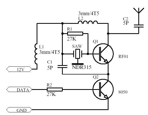
There are many forms of wireless transmission circuits using acoustic meter resonators. Here is another circuit. This circuit was made after I referred to the article in the electronic newspaper three years ago and combined with the actual sample of the module introduced in the article. After mass production, some parameters have been improved, and now this product is really very good. But now there are too many imitation products of this kind, and the quality varies greatly, but because it is relatively simple, I think it is still necessary to get it out for everyone. I have found many similar circuit diagrams on the Internet, but Some of them are trapped. I hope everyone should pay attention to learn to identify some bugs by themselves. For this module, I have not tested the absolute power of its wireless transmission, but we drove the car over the distance on the highway. It cooperates with the ordinary 315M super regenerative receiving module to reach a distance of 800 meters, although my circuit As long as the value of the 8050 base resistance is reduced, the communication distance will be increased to 1200 meters or even farther, but after a lot of experiments have proved that it is not very reliable, the reason is not very clear to me, there may be two reasons, one It is 8050 that when R2 is small, there is a slight turn-on, which causes the transmission cannot be quickly cut off. Another is that R2 is very small, the 8050 turn-on current is relatively large, it may be a disturbance to the power supply, but can not meet the start-up requirements. I once doubted whether my circuit was a good match, so I bought a lot of similar modules named 1500 meters, and found that they also have the same unreliability, which is generally manifested as occasional vibration or baud rate less than 2K. Later, I increased the R2 resistance. When it is greater than 15K, the emission has been normal, and the distance is about the same as 27K, so I use this resistance now. For the L1L2 here, I use a 0.8mm drilled enameled wire with a 3mm drill It's made from 4 rounds and half-born ? |

Follow WeChat

Download Audiophile APP

Follow the audiophile class
related suggestion
This article mainly introduces the infrared diode emission circuit diagram (acoustic and optical alarm / TPS604 / wireless headset infrared emission circuit in detail). Wireless Headphones...
This article mainly introduces the 315m wireless transmission and reception circuit diagram (wireless transmission / wireless reception circuit diagram in detail). The radio remote control circuit consists of radio ...
This article mainly introduces the 1000 meters wireless transmission circuit diagram Daquan (single tube oscillation C8050 / high frequency triode / T630 FM transmission circuit ...

The ultrasonic generator consists of two piezoelectric plates and a resonance plate. When a pulse signal is applied to its poles, and its frequency is equal to the natural oscillation of the piezoelectric chip ...

In order to improve the communication and information exchange capabilities of modern weapon systems in harsh electromagnetic environments, make full use of the natural secrecy of the laser and reduce the radio frequency ...

The NPX I chip has 4 KB of user programmable space, 4 KB of custom ROM, and a 2D LF input stage. Various sensors ...
The system selected is the AT89C51 chip of the 51 series. AT89C51 is a programmable erasable read-only storage with 4k byte flashing ...

The tire module circuit uses the intelligent embedded sensor MPXY8300 of FREESCALE. This series of sensors integrates the company's ...

The following figure is the schematic diagram of the wireless remote control transmitter and receiver circuit. Figure 1 The schematic diagram of the wireless remote control transmitter circuit. Figure 2 The schematic diagram of the wireless remote control receiver circuit.

The transducer transmits and receives ultrasonic waves directly below the bottom of the ship to detect targets under the bottom of the ship. The difference is that the former uses fish as the main detection ...

The four-way remote control transmitter circuit is mainly composed of a 315MHz wireless data transmission module and a code integrated PT2262.

Electronic enthusiasts provide you with a remote control toy car launch circuit, hoping to inspire your creativity.

The video signal is firstly amplified by a reverse phase, and then input to the AM modulation stage through the emitter follower; the transmission frequency is generated by the LC high-frequency oscillator and sent to the AM modulation ...

BA1404 Stereo FM transmitter circuit (power amplifier, field strength circuit)

LM317 AFM transmitter Transmitter circuit made by LM317
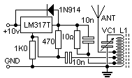
2m FM 144M-148M transmitter circuit Near-Earth Telemetry (Morse Code ...

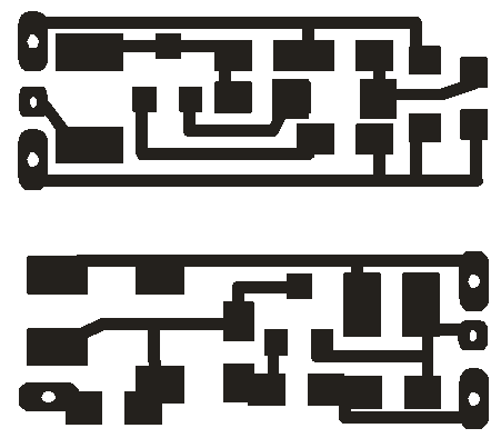
This SMD FM transmitter has ...
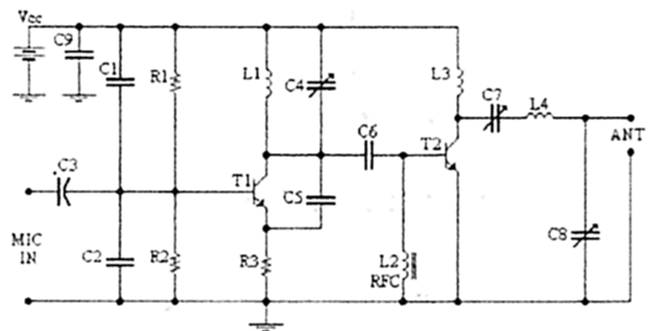
4W FM transmission circuit diagramTECHNICAL CHARACTERISTICS: Stabilise ...
Ultrasonic transmission circuit design of low-voltage power supply Ultrasonic application fields are very broad, such as military sonar technology, industrial nondestructive testing, testing ...

Simple FM transmitter circuit 1.5V-10m3V-30m working current: <= 0.5mA24 # enameled wire at 0.6c ...

96Mhz FM transmitter circuit diagram

56M video image transmission circuit diagram The radio frequency transmission circuit generates a frequency of 56MHz through a three-point capacitor, and the image signal is collected by the camera ...

On-site signal fiber transmission transmitter circuit

Voice modulation optical transmission circuit
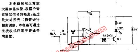
50khz frequency light emitting circuit
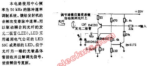
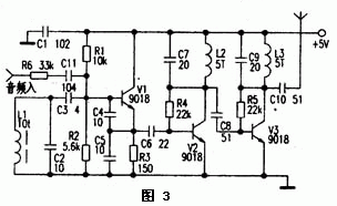
Figure 3 is a practical 50m FM wireless headset transmitter part of the circuit. The circuit is divided into
â—† Overview of circuits Many homes now have televisions
![[Photo] Practical home TV station transmission circuit](http://i.bosscdn.com/blog/20/06/41/719132274.jpg)
The working voltage is 9V, the working current is 2 ~ 6mA, the component parameters are as shown in the figure, BG1 ...

The low-power FM transmitting circuit introduced in this article, due to the use of a dedicated transmitting tube, the degree of modulation ...
![[Photo] AM audio transmission circuit](http://i.bosscdn.com/blog/20/06/41/5205911625.gif)
![[Photo] Remote FM transmitter circuit made with LM389](http://i.bosscdn.com/blog/20/06/41/5205320565.gif)
![[Photo] 8050 single tube launch circuit](http://i.bosscdn.com/blog/20/06/41/5205224485.gif)
3-Meter Zender (100-108Mhz / 10-15 ...
![[Photo] 100-108Mhz / 10-15W launch ...](http://i.bosscdn.com/blog/20/06/41/5205040737.gif)
For an amateur radio enthusiast, getting a good FM transmitting circuit is like picking up ...
![[Photo] 1000-meter single-tube oscillation (C8050) FM transmission ...](http://i.bosscdn.com/blog/20/06/41/5204719922.gif)
The working voltage of this circuit is 9V, working ...
![[Photo] Simple frequency modulation transmitting circuit with stable frequency](http://i.bosscdn.com/blog/20/06/41/520451129.jpg)
The author refers to the "simple and easy-made integrated FM speech" published in the 21st issue of "Electronic Newspaper" in 1993 ...
![[Photo] BA1404 / 1404F FM stereo transmission ...](http://i.bosscdn.com/blog/20/06/41/520409234.gif)
BA1404 is one of the few FM transmitting integrated circuits, which makes up for the discrete in the past ...
![[Photo] BA1404 Stereo FM Transmitting Circuit](http://i.bosscdn.com/blog/20/06/41/520400725.jpg)
