With the increasing demand for higher-precision RTLS, developers have found themselves trapped in complex, high-precision methods such as two-way ranging or time-difference-of-arrival (TDOA) positioning.
Decawave's integrated modules and software provide developers with a simpler RTLS solution that can more easily provide more accurate positioning results.
This article reviews RTLS applications and algorithms including bidirectional ranging and TDOA, and discusses the related implementation tradeoffs of different RTLS methods. Later, this article will introduce a Decawave UWB transceiver that focuses on the specific requirements for designing with this device. Finally, this article will discuss Decawave's software architecture and accompanying firmware development, illustrating specific ways to develop user applications on the Decawave platform.
Role of the RTLS System Precision RTLS has become an effective method for determining or tracking the location of people and mobile assets in office buildings, warehouses, manufacturing plants and assembly lines. According to this method, a mobile object (tag) exchanges information with a fixed-position device (positioning point) using the standard format and UWB technology specified in the Low-Rate Wireless Personal Area Network (LR-WPAN) standard IEEE 802.15.4-2011. By determining the distance between the tag and multiple anchor points, the relevant application can determine the position of the tag relative to these known anchor points and thus determine the absolute position of the tag.
RTLS Method The RTLS application uses several methods to determine the distance. In the simplest approach, an application or tag can use the Received Signal Strength Indicator (RSSI) parameter provided by most transceivers to evaluate the tag's position relative to the transmission fix. Because there are many factors that may affect the link budget, this method can only provide a rough estimate of the location. In contrast, many emerging applications based on RTLS require that the absolute position be determined to a precision of a few centimeters.
High-precision RTLS uses the time-of-flight method, and this type of method is hardly affected by the large variations in RF signal strength. According to this method, the position of the tag can be determined by measuring the time required for the radio frequency signal to pass from the tag to a plurality of positioning points. With known propagation delays when RF signals travel through the air, RTLS applications can convert flight time to distance.
For example, if the flight time between the tag and all three anchor points is exactly the same, then it stands to reason that this happens only when the tag is equidistant from these anchor points. Since the application knows the exact location of each anchor point, it can determine the absolute position of the tag.
However, to measure the propagation time of the tag transmitter, the location point receiver needs to use the same time base as the tag in order to correctly evaluate the time information embedded in the tag message. If the time base of the anchor point lags or precedes the time base of the tag, the calculated distance will be closer or farther than the actual distance, respectively.
An RTLS method addresses this issue in a simple manner, namely, time synchronization of the tag transmitter and the location point receiver to ensure that each location point receives the same time base as the tag. Even in the best case, achieving time synchronization is challenging, and it is simply not practical in RTLS applications where wireless tags move around.
Another method, TDOA, only synchronizes the anchor points, eliminating the difficulties associated with the synchronization of mobile tags. To determine the location, the RTLS application uses the difference in the arrival times of the tag signals measured across multiple anchor points. For example, consider the example where the previous three positioning points (A1, A2, and A3) are distributed equidistant around one tag. After the label moves, if the TDOA of each anchor point is found to be 0, 1 nanosecond (ns) and 0, respectively, it means that the label has moved about 30 centimeters (cm) away from the straight line of anchor point A2 (assuming radio frequency). The speed of light is the speed of light. The TDOA's anchor point synchronization requirements are much less difficult than trying to synchronize anchors and tags. But even so, the accuracy of this method still depends on highly accurate synchronization. Even a nanosecond sync difference can result in a few centimeters difference in position measurement.
Two-way Ranging The two-way ranging RTLS method does not require exact time synchronization at all, but introduces transmission capability requirements in the tag. This approach circumvents the uncertainty associated with different time bases by supporting the exchange of timing information between tags and anchors. Instead of synchronizing their time bases, tags and anchors use a short, two-way information transfer protocol to accurately determine flight time and accurately calculate tag positions.
According to this method, the tag transmits a short identification signal and “brightly identifies†to the surrounding anchor points. The anchor point of each received tag's initial identification information then cooperates with the tag to perform a short two-way data exchange for determining the time of flight without considering the time base difference between the anchor point and the tag.
Decawave defines this process from the perspective of the discovery and ranging phases in its two-way ranging RTLS protocol (Figure 1). During discovery, the tag periodically transmits a short identification signal (ie, a blink signal) and waits for a response from the anchor point. After the tags and anchors are identified with each other, the paired tags and anchors use a short two-way information exchange that contains the information needed for ranging.
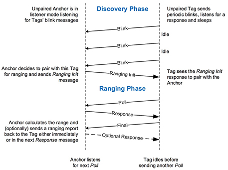
Figure 1: In Decawave's two-way ranging protocol, tags and anchors exchange a series of messages to complete the discovery and provide ranging information. (Source: Decawave)
For developers, the challenges of implementing these precisely designed message exchange protocols and their underlying UWB radio subsystems can be daunting. With the Decawave DWM1001 module, however, developers can quickly add precise RTLS functionality to their applications with minimal extra work.
Integrated RTLS Module The Decawave DWM1001 module implements RTLS in its entirety, integrating the Decawave DW1000 UWB transceiver with a Nordic Semiconductor NRF52832 wireless MCU and an STMicroelectronics LIS2DH12 3-axis motion sensor. Although the DW1000 provides RF signaling capability in compliance with the IEEE 802.15.4-2011 standard, the NRF52832 MCU still implements its embedded firmware for RTLS applications. The LIS2DH12 sensor plays an important role in power management.
In any complex RF application, RF design often brings some of the most daunting challenges, especially in mobile applications that require very little packaging and very low power consumption. The DWM1001 module addresses these issues by leveraging the integrated RF design provided by the DW1000 transceiver (Figure 2).
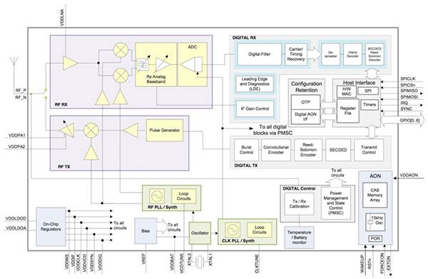
Figure 2: The Decawave DW1000 transceiver integrates radio signal paths and digital control logic to provide a complete IEEE802.15.4-2011 compliant system. (Source: Decawave)
The DW1000 provides a complete UWB transceiver with an integrated RF front end that can support six IEEE 802.15.4-2011 channels from 3.5 GHz to 6.5 GHz, with standard bit rates of 110 Kb/s, 850 Kb/s, and 6.81 Mb/s. The device's integrated digital control subsystem manages the transceiver and supports bidirectional ranging and the TDOA RTLS system with positioning accuracy of up to 10 centimeters. With integrated one-time-programmable memory (OTP), developers can store data for calibration and error correction, while the device's configurable uninterruptible memory (AON) is retained during the device's low-power state described below. Configuration Data.
During operation, the device sends and receives standard IEEE 802.15.4-2011 frames containing the Synchronization Header (SHR), Physical Layer Header (PHR), and up to 127 words that make up the overall Physical Layer Service Data Unit (PSDU). Section data. In addition to standard frames, the device also supports a proprietary frame format that provides up to 1023 data bytes for applications that need to send larger data payloads but do not require compliance with the IEEE 802.15.4-2011 standard.
For standards-compliant applications, developers can choose from a range of operating modes to meet specific bi-directional ranging and TDOA operation use cases. These modes of operation precombine the data rate, payload size, and preconfigured preamble length. For example, modes suitable for remote applications combine lower data rates and longer preambles that facilitate discovery and ranging in interfering or weaker signals. Conversely, modes with higher data rates and shorter preambles support short-range applications. Other modes support the characteristics of such remote and short-range applications with different sizes of data payloads.
Minimizing Power Consumption In practice, developers will choose a mode of operation where the frame size is as short as possible to minimize overall power consumption and allow the device to quickly return to a low-power state. The DW1000 offers a variety of low power modes. During the non-active period, the device can be put into standby mode, the current consumption of this mode is only 19 milliamperes (mA). If long-term inactivity is required, developers can place the device in a low-power sleep mode with a current consumption of only about 1 microamperes (μA) while the deep-sleep mode consumes no more than 100 nanoamperes ( nA) (typical 50 nA).
However, as with any RF design, the transceiver consumes significantly more power during operation. For example, to transmit IEEE802.15.4-2011-compliant frames, longer frame components such as synchronization headers and data packets consume most of the power (Figure 3).
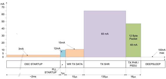
Figure 3: The RTLS frame transmission of the Decawave DW1000 will result in a significant increase in the power consumption of the individual frame components, prompting designers to start looking for the mode of operation with the shortest useful synchronization header and data payload. (Source: Decawave)
The power consumption associated with receiver operation is even greater, which presents a more difficult challenge for power-constrained designs (Figure 4). Developers can set the DW1000 to resume one of the low-power states after sending or receiving operations. Even so, the nature of the standard protocols and frames makes little choice for reducing power consumption during frame operations.
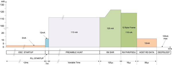
Figure 4: Since the preamble look-up phase has a longer duration, the power requirements required to receive the frame are even higher than the transmission operation. (Source: Decawave)
The DW1000 offers unique power-saving features to reduce power consumption in the preamble RX phase. Developers can program a special preamble sniffing mode for the device instead of keeping the receiver active. In this case, the DW1000 periodically powers up the receiver, looks for the preamble, and resumes standby if no preamble is found (Figure 5).
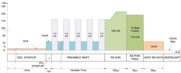
Figure 5: Developers can use the DW1000's sniffing function to reduce power consumption associated with receiver operation, allowing the device to alternate between standby and receiver activity modes. (Source: Decawave)
Functions such as preamble sniffing are especially important for battery-powered tags. Developers can apply a variety of power-saving methods during RTLS operations. One of the methods utilizes the different known delays that exist in the bidirectional ranging protocol shown in FIG.
For example, during the discovery phase, the ranging initialization response of the anchor point to the tag “blink†occurs after a certain delay. Developers can estimate this delay based on frame rate and other parameters, measure its actual value in its anchor design, and even build a specific response delay time in its anchor design. The developer can then safely keep the tag receiver closed for the expected delay time, search for the response and turn the receiver on, and if the ranging initialization response does not arrive within a reasonable window, close the receiver again.
Similarly, developers can take steps to limit the amount of time the radio needs to stay on during range finding. For example, developers can preload all required data in the device and use direct memory access to speed up data transfer between the DW1000 and host memory.
Although these low-level optimizations can increase incremental power savings, developers can further improve energy savings by dynamically changing the location update rate. After the label stops moving, there is no need to continue the high-energy discovery and ranging phase. The tag can safely enter a low-power sleep state and wake up after it starts to move, continuing to update at a nominal rate.
By integrating the LIS2DH12 motion sensor, the DWM1001 module supports dynamic rate adjustment and supports two motion-related modes of operation: low power consumption and response mode. Developers can configure this module so that when the LIS2DH12 senses that the module is stationary, the DW1000 transceiver operates in a low-power mode. When the LIS2DH12 detects a move, the transceiver can revert to the response mode and the DW1000 transceiver will resume normal update rate.
Developers can further optimize their RTLS application to control the update rate based on the speed and acceleration of the object. For example, a slow-moving tag may require only a low update frequency to maintain the necessary positioning accuracy. As tag speeds increase, applications can respond by increasing the rate of location updates.
RTLS development In addition to supporting RTLS features such as dynamic update rates, this module also provides basic RTLS development advantages. For example, the DW1000 transceiver employs several specific interface requirements for power supply decoupling, antenna network matching, reference oscillators, and other components (Figure 6). Similarly, the NRF52832 wireless MCU and LIS2DH12 motion sensor also have their own interface design requirements.
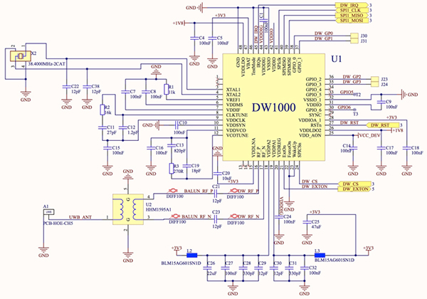
Figure 6: The Decawave DW1000 transceiver uses stringent interface requirements to ensure reliable power, RF, and timing signals. (Source: Decawave)
Although advanced devices such as these use a highly simplified design, designers may face severe challenges in optimizing the integration in designs that require the highest performance at the lowest power. The DWM1001 module will require integration to reduce the connection of at least a few power, ground, and digital interfaces (Figure 7).
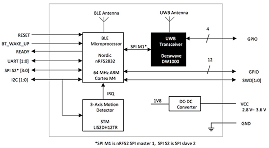
Figure 7: The Decawave DWM1001 module simplifies RTLS development by providing a fully integrated design that integrates the DW1000 transceiver with wireless MCUs and motion sensors. (Source: Decawave)
Software Model Similarly, the module greatly simplifies software development and integration with its pre-installed Decawave Positioning and Networking Stack (PANS) library firmware. The PANS library is built on the MCU's on-chip Bluetooth low energy (BLE) stack and includes the open source eCos real-time operating system (RTOS), a network layer, and support for BLE services, RTLS management services, and two-way ranging (TWR) positioning engines. Several application layers (Figure 8).
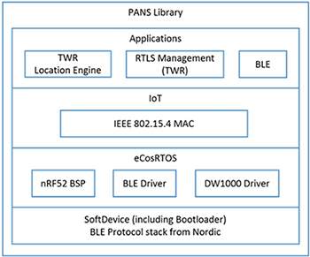
Figure 8: The Decawave Positioning and Networking Stack (PANS) library combines the Bluetooth stack, RTOS, network layer, and application services layer to provide a feature-rich RTLS application platform. (Source: Decawave)
When the firmware application is running on an MCU built on the DWM1001, the developer accesses the PANS library through a comprehensive application programming interface (API), which provides the appropriate entry points for each PANS module to configure and control the module. The PANS API contains several API sets for individual modules, including developer C code, serial interface libraries (CPI and UART), and the BLE library (Figure 9).
The application connects directly to these four high-level APIs, which in turn translates these calls into common API calls to the PANS library through a common API parser to enable access to the PANS library. In this role, the common layer provides a common interface to the PANS library.
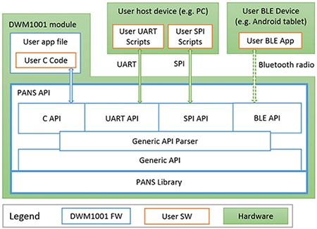
Figure 9: Decawave provides PANS library access through a wide range of APIs, each providing simple access to the underlying threaded execution model. (Source: Decawave)
Threaded architecture In this architecture, the DWM1001 firmware software uses a threaded model, essentially providing a separate thread for each module and library in the stack. Each of the four modules at the top of the stack passes the resolution request to the generic API resolver thread, which verifies each request and invokes the PANS library to generate the appropriate response. The generic API thread then uses the callback function provided when the call was made, and returns the result to the calling module at the top of the stack.
Although this multi-tier system seems to be very complex, it is relatively simple to see from the developer's programming model. Using API calls with independent thread callbacks helps optimize resource utilization and overall application performance.
At the same time, the underlying complexity is also masked by a set of APIs that translate advanced application-oriented calls into specially-threaded, optimized operations that interact with the DWM1001 hardware. The DWM1001 programming model further simplifies the interaction of developers with this system. Developers use the system's built-in user-specific application threads without interacting with multiple threads and APIs.
As shown in Listing 1, developers use a simple API call (dwm_thread_create) to call a user application thread that registers a user application thread function (app_thread_entry).
Copy /* Create thread */
Rv = dwm_thread_create(THREAD_APP_PRIO, app_thread_entry, (void*)NULL, "app", THREAD_APP_STACK_SIZE, &hndl);
APP_ERR_CHECK(rv);
/* Start the thread */
Dwm_thread_resume(hndl);
Listing 1: With the Decawave threading model, developers can register and launch their user application threads with a simple API call. (Source: Decawave)
Decawave provides user application threads and callback sample code. This sample code is bundled in an Oracle Virtual Box virtual machine image that contains the complete tool chain, libraries, and a simple example application. This package is designed to work with the Decawave DWM1001-DEV development board connected to a Windows PC and provides a framework for creating custom RTLS application software.
The sample code included in this package demonstrates the key user thread function design patterns (Listing 2). In this example, the user thread function (app_thread_entry) sets application-specific configuration parameters (such as update rate) and registers the callback with the API function dwm_evt_cb_register and its callback function name (on_dwm_evt). After registering the callback, the sample thread enters the main loop – a series of deferred function calls in this example to reduce resource utilization.
Copy void app_thread_entry(uint32_t data)
{
.
.
.
/* Update rate set to 1 second, staTIonary update rate set to 5 seconds */
APP_ERR_CHECK(dwm_upd_rate_set(10, 50));
/* Register event callback */
Dwm_evt_cb_register(on_dwm_evt, 0);
.
.
.
While (1) {
/* Thread loop */
Dwm_thread_delay(100);
}
}
Listing 2: In this snippet of the Decawave Firmware Development Kit, the sample code shows the basic design pattern for registering callbacks and executing main loops in user application thread routines. (Source: Decawave)
The example callback function (on_dwm_evt) demonstrates the basic event handler called when an event occurs (Listing 3). In this code example, the only valid event is the new location information available (DWM_EVT_NEW_LOC_DATA). In the handler for this event, the code demonstrates a simple call set for retrieving the location data generated by the available anchors. After completing its event processing task, the callback goes directly to sleep.
Copy /**
* Event callback
*
* @param[in] p_evt Pointer to event structure
* @param[in] p_data Pointer to user data
*/
Void on_dwm_evt(dwm_evt_t *p_evt, void *p_data)
{
Int i;
Switch (p_evt->header.id) {
/* New locaTIon data */
Case DWM_EVT_NEW_LOC_DATA:
/* Process the data */
Printf("T:%lu ", dwm_sysTIme_us_get());
If (p_evt->data.loc.p_pos == 0) {
/* LocaTIon engine is disabled */
} Else {
Printf("POS:[%ld,%ld,%ld,%u] ", p_evt->data.loc.p_pos->x,
P_evt->data.loc.p_pos->y, p_evt->data.loc.p_pos->z,
P_evt->data.loc.p_pos->qf);
}
For (i = 0; i < p_evt->data.loc.anchors.dist.cnt; ++i) {
Printf("DIST%d:", i);
Printf("0x%04X", (unsigned int)(p_evt->data.loc.anchors.dist.addr[i] & 0xffff));
If (i < p_evt->data.loc.anchors.an_pos.cnt) {
Printf("[%ld,%ld,%ld]",
P_evt->data.loc.anchors.an_pos.pos[i].x,
P_evt->data.loc.anchors.an_pos.pos[i].y,
P_evt->data.loc.anchors.an_pos.pos[i].z);
}
Printf("=[%lu,%u] ", p_evt->data.loc.anchors.dist.dist[i],
P_evt->data.loc.anchors.dist.qf[i]);
}
Printf("");
Break;
Default:
Break;
}
/* Indicate the application has finished the tasks and can now */
Dwm_sleep();
}
Listing 3: The callbacks for this Decawave sample application fragment demo provide a basic event handler for accessing the new location data. (Source: Decawave)
For example, in a full Internet of Things (IoT) RTLS application, tags and anchors communicate via a routing anchor that is linked to an Internet-connected gateway system. Decawave is releasing its second firmware package, which will provide gateway support via a Linux-based package and will use familiar IoT messaging protocols including HTTP, WebSockets, MQTT, and AMQP.
Summary RTLS plays an increasingly important role in a wide range of applications. Although the RTLS method is based on a relatively simple principle, the implementation of these methods requires complex RF/analog design, system design, and software development to ensure the highest accuracy is achieved with minimal power consumption.
The Decawave DWM1001 module provides a complete RTLS system that combines Decawave's integrated DW1000 UWB transceiver with wireless MCUs and motion sensors. With this module and supporting software packages, developers can quickly implement high-precision battery-powered RTLS systems.
Yooz Pod has 38 fruit flavors, Yooz Kit has ordinary solid color, gradual color, illustration Kit, disposable yooz, small and light
Hot Selling Original Yooz Vape Kit ZERO2 Essential Device
Looking for Vape Kit? We provide you with the most cost-effective Yooz Vape kit, so that customers can enjoy a better new smoking experience at the most affordable price.Yooz Vape Kit ZERO 2 Device is the Replaceable Vape rechargeable battery part of the YOOZ ZERO 2 Vape Pod System Vape Kit, featuring a double leak proof structure design, lightweight and no fire button design. The battery capacity of the device is 350mAh. It allows about 300 puffs with the battery fully charged. Middle of the device is an intelligent [Y" shaped LED battery life indicator, it will let you know when you need to charge.
Main Features:
1. Creates extremely dedicated atomized and fume oil enriched taste nicotin salt brings you stronger throat experience.
2. Patented double leak proof structure design pod.
3. 30 minutes charging provide you with 24 hours heavy use.
YOOZ Vape kit
Specifications:
Brand: YOOZ Vape
Battery Capacity: 350mAh
Full Charge:30 minutes
Size: 88.5x21x11.5mm
Package Contents:
1* YOOZ ZERO 2 Device
1* Micro USB Charging cable
1* User Manual


YOOZ Vape,YOOZ Disposable Vape,YOOZ Pod Premium Ingredients,YOOZ Mini Pod Kit,YOOZ Vape Pod
TSVAPE Wholesale/OEM/ODM , https://www.tsecigarette.com