The design idea of ​​the tower solar thermal power system was proposed by the former Soviet Union in the 1950s. In 1950, the Soviet Union designed the world's first small-scale experimental device for tower solar thermal power stations and conducted extensive and basic exploration and research on solar thermal power generation technology. According to incomplete statistics, in 10 places from 1981 to 1991, more than 20 megawatt-scale solar thermal power experimental power stations were built around the world, of which the main form was a tower-type power station with a maximum generating power of 80MW. In July 2013, China's Qinghai Zhongkong Delingha 50MW Tower Solar Thermal Power Station Phase I 10MW project was successfully integrated into the Qinghai Power Grid to generate electricity, indicating that China's self-developed solar thermal power generation technology has taken a solid step toward commercialization.
Tower-type thermal power generation principleThe concentrating solar power generation technology in which the absorbed sunlight concentrates on the top of the tower and heats the heat transfer working medium to generate electricity, does not require a pipeline transmission system, reduces heat loss, has high system efficiency, and facilitates storage of heat. The tower working medium can use air, water or water vapor, molten salt, and the like.

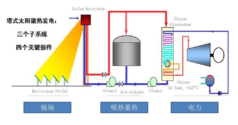
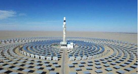
Tower solar thermal power generation system is to build a tall central absorption tower on the open ground. An absorber is installed on the top of the tower, a certain number of heliostats are installed around the tower, and sunlight is collected through the heliostats. A high temperature is generated in the cavity of the receiver at the top of the tower, and then the working fluid passing through the absorber is heated to generate high-temperature steam to drive the turbine to generate electricity. That is, the tower solar thermal power generation system uses a large number of plane reflector arrays to reflect solar radiation to the solar receiver placed on the top of the tower. The heating medium generates superheated steam and drives the turbine generator set. Tower solar thermal power generation is Turn light energy into heat energy, and then work to generate electricity through the traditional thermal cycle. The tower solar thermal power generation system is mainly composed of a mirror field and a fixed-day system, an endothermic and heat transfer system, a thermal storage system, and a conventional island power generation system. The mirror field and the sun setting system track the sun and accurately reflect the sunlight to the heat sink. The collector on the tower converts the specularly reflected high heat flux radiant energy into the thermal energy of the working fluid.
1ã€heat collection systemThe heat collection system includes a single mirror, focusing device, receiver, tracking mechanism and other components.
2, heat transfer systemThe heat transfer system is mainly the heat energy collected by the heat transfer system. Heat energy is transferred to the thermal storage system using a heat transfer medium. The heat transfer medium is mostly water, thermal oil and molten salt.
3, heat storage and heat exchange systemPhoto-thermal power generation technology fully embodies the advantages of contrast photovoltaic power generation technology in heat storage and heat exchange systems. It will store solar heat energy. It can generate electricity at night, and it can also adapt to the grid to generate electricity according to the local electricity load. The heat storage device is often composed of a vacuum heat insulator or a heat accumulator covered with a heat insulating material. The requirements for heat storage medium in the thermal storage system are: high density of energy storage, abundant sources and low prices, stable performance, non-corrosiveness, good safety, large heat transfer area, good thermal conductivity of heat exchanger, and heat storage medium Better stickiness. At present, China is studying a variety of new technologies and new materials for heat storage, and some experts have proposed the use of ceramics and other inexpensive solid heat storage in order to achieve the effect of reducing power generation costs.
4, power generation systemThe turbine generator set used in large-scale solar thermal power generation systems, because its temperature level is basically the same as the thermal power generation system, can use conventional steam turbines; still need to configure the corresponding demineralized water system and auxiliary machine circulating water system. The cooling method currently used in the gas-condensing device is mostly air-cooled. Although the photo-thermal technology power generation system is similar to a thermal power generation system, it still has certain differences. This requires the turbine to have features such as frequent start-stop, quick start, low-load operation, and high efficiency.

As with the traditional commissioning of thermal power plants, tower-type solar thermal power generation is also based on the system to carry out sub-system commissioning and complete start-up commissioning:
1. As with traditional power plants, the commonly used power and chemical water must be completed, and the entire construction starts normally.
2. Installation of mirror field and fixed-day system and debugging of automatic control. The mirror field serves as the energy source for the CSP plant. After completing a single mirror installation, the single-mirror control system and the commissioning commissioning of the actuator must be completed. After the mirrors of the entire mirror field are installed and adjusted, the entire mirror field is set to date. The tracking and debugging of the system and the debugging of the mirror field automation include the input ratio of mirrors in the startup process of the power plant, self-protection against adverse natural conditions, testing of the mirror's regular self-checking function, and regular cleaning of the post-operation.
3. The heat transfer system is currently divided into single loop and two loop heat transfer systems.
3.1 A single circuit uses hydraulic fluid as an example. The hydraulic mass tower thermal power generation technology sends feedwater to a heat absorber at the top of the tower through a feed pump. It is heated and evaporated in a heat sink to produce saturated steam, which drives the turbine to generate electricity. The system generates electricity; another superheated steam absorber is added to the top of the tower to superheat the high pressure steam and then drive the turbine generator system to generate electricity. This single loop is similar to a conventional thermal power system. Before the test run, the system needs to perform corresponding water flushing and blow pipe work of the entire steam pipe, so as to avoid the pipeline impurities from entering the steam turbine and causing damage to the steam turbine.
3.2 Two-loop heat transfer system According to the heat-collecting field, the heat transfer medium is mainly divided into molten salt and compressed air. At present, the most commonly used binary molten salt is mainly composed of NaNO3 and KNO3. The system flow is 290 °C cold molten salt is withdrawn from the cold storage tank to the absorber located at the top of the tower, heated to 565 °C, and then by gravity back to the hot-melt salt storage tank, and then pumped out by the hot salt pump After the steam generator system generates high temperature and high pressure steam to drive the turbine power generation system to generate electricity. The key to the commissioning of this system includes the stable operation of the molten salt pump, the low-temperature solidification of the molten salt cycle, the first salt and salt in the molten salt, and the thermal insulation of the molten salt tank system. Because the molten salt is irreversible once it is solidified in the system, it is destructive to the system. Therefore, the stable control of the molten salt pump is currently mostly designed for frequency conversion control. A boiler feedwater control valve similar to a conventional power plant is added to the upper tower pipeline, and the molten salt temperature at the outlet of the collector is strictly controlled through the flow. Molten salt circulation low temperature solidification problem, according to the molten salt melting point is generally more than 200 degrees Celsius, in order to avoid the sun after the heat sink and pipe melt salt coagulation requires a lot of energy consumption. At sunset, the molten salt in the entire pipeline is recovered to the molten salt tank; when the system is re-run the next day, the entire pipeline is preheated by surrounding the resistance wire on the molten salt pipeline, and the molten steel is filled with the predetermined temperature. salt. The heat absorber is preheated by the heliostat system. Before the system is started, some heliostats are aligned with the heat absorber, and the molten salt and operating system are charged before the temperature rises above 260° C., thereby avoiding molten salt. Solidify in the system.
The initial salt and salt input of the molten salt require the salt to be introduced into the system after the entire mirror field and heat collection system has been put into operation. The initial salt is a powdered solid and is initially heated with steam until the solid state melts. The salt melts at 220°C (melting point) and is liquid. It is sent to an electric heating molten salt furnace after being pressurized by a molten salt preparation pump, heated to 290°C and sent to a cold-melt salt tank for use by the system. When sufficient quantities are prepared, after the cold molten salt tank reaches a certain liquid level, the solar energy collection zone is started to circulate, the molten salt is heated to a higher temperature (up to 565° C.) by the collector, and it is stored in the hot molten salt tank cyclically. in. When the prepared molten salt reaches a sufficient quantity, a part of the high temperature molten salt is sent to the hot molten salt tank, and then the electric valve is opened to the molten salt preparation tank, and the molten salt is put into the molten salt preparation tank, and a certain amount of solid molten salt is added. Mixed with high-temperature molten salt melted at 290 °C liquid molten salt, due to an increase in the amount of molten salt, open the two molten salt preparation pump pressure, the electric heating of the molten salt furnace bypass to the cold-melt salt tank. As a result, the steam heating molten salt furnace and the electric heating molten salt furnace can be deactivated, and the molten salt can be prepared by solar heating. With the gradual increase of the liquid molten salt prepared, the solar energy collecting zone can be gradually added to the cycle until all the solar heat collecting zones are put into circulation, and finally the molten salt of the heat storage part is prepared. At this point, the entire first salt melt salt work was completed. Because of the low-temperature solidification properties of molten salt, binary salt condensation protection is necessary because once the crystals appear in the tank, it cannot be melted, and after a large area of ​​solidification, the power plant cannot be operated. The damage of the entire tank is irreversible. of. First, the bottom of the molten salt tank is divided into the following parts from the bottom up: concrete layer, heat insulation layer, foam layer and heat-resistant (fire-resistant) layer. Second, through two methods, one is to carry out the circulation in the tank through the molten salt pump; the other is to use the electric heater in the heat storage tank for heating protection. There are usually multiple sets of electric heaters in each tank. When the temperature decreases, the electric heating system is automatically put into operation.
3.3. Steam Generator System
For the two-loop system, the steam generation system exchanges heat with hot molten salt and water to generate high-temperature and high-pressure superheated steam to drive the steam turbine unit and drive the generator to work. The system mainly includes: preheater, evaporator, superheater. The heat exchangers are all shell and tube type, in which the tube side of the preheater and the superheater is water/steam, and the side of the evaporator tube is molten salt, and the corresponding shell sides are molten salt and saturated water, respectively. Solar power plants feature that the system may need to start and stop daily, including steam generation systems. Of course, when the power station does not have enough heat storage, the heat exchanger needs to be warmed up when the daily system is restarted, so that the temperature of the heat exchanger is evenly distributed before it enters the normal working state, and the high pressure steam generated is used to preheat the steam turbine and Steam line. Of course, when the temperature and pressure reach the steam turbine start-up requirement, the steam turbine will enter the normal start-up operation state. Preheating of the system requires auxiliary steam, which is generated from the surplus of the heat storage system. If the system has a large-capacity heat storage system, the system will operate for 24 hours in good weather, without considering the warm-up process of the steam generator system. Therefore, the two-loop system also involves the blow pipe work of the steam system, which is achieved by the high temperature and high pressure steam generated by the steam generator.
3.4 Conventional Island
After the main steam generated by the steam generator is drawn from the superheater, it is sent to the steam turbine for work. The exhaust steam after the work is discharged into the condenser. After doing work, the steam turbine converts the thermal energy of the steam into kinetic energy and drives the generator to generate electricity. The generator converts the kinetic energy into electrical energy. Steam turbine low-pressure cylinder exhaust steam is condensed into water in the condenser, condensate water enters the condensate pump, the boosted condensed water passes through a shaft seal cooler, a low-pressure heater, and finally enters a deaerator, and the deaerator has heating and removing. Oxygen and water storage function. After the deoxygenated feedwater is boosted by the feedwater pump, it flows through the high pressure heater and enters the preheater of the steam generation system system in two ways and then enters the steam generator. Complete the entire cycle. The debugging work of the entire conventional island is consistent with the traditional thermal power and will not be introduced here. After completing the above-mentioned commissioning operations of the respective systems, the entire system has the conditions for production and operation after the entire system is ready for operation.
Antenk's High Definition Multimedia Interface (HDMI) connectors and cable assemblies are a series of products that provide an uncompressed digital link between video and audio in a single digital interface connection. Typically they are used with digital versatile (DVD) players, digital television (DVI), set top boxes and other audiovidual devices to consolidate interfaces and eliminate multiple cable assemblies. Adam Tech's HDMI series are small, easy to to use interconnects that can carry up to 5 Gbps of combined video and audio in a single connector/cable.

HDMI Connector Overview
High Definition Multimedia Interface (HDMI) connector and cable assemblies deliver the highest quality, high-definition content by providing an uncompressed digital connection from any audio/video source to an audio and/or video monitor over a single cable. The single interface of the Antenk HDMI connector makes it economical and easy to use as it combines both video and multi-channel audio into a single-port connection, eliminating the cost, complexity, and confusion of multiple cables used in A/V systems.
Micro HDMI connectors offer all the advantages of the HDMI standard 1.4 specification and are half the size of the industry Mini HDMI connector. Antenk`s Micro HDMI features a miniature footprint and low-profile height, which offers significant space savings, delivering equivalent mechanical strength and electrical characteristics.
Micro HDMI cable assemblies feature a stylish and compact overmold design and are available in a variety of customizable cable lengths.
HDMI Connector Types
Standard HDMI (HDMI Type A)
Extended Pin HDMI (HDMI Type B)
Mini HDMI (HDMI Type C)
Micro HDMI (HDMI Type D)

HDMI Connector Features and Benefits
Compact and user-friendly design
Meets consumer equipment needs
Triad signal layout
Low impedance mismatch
Satisfy HDMI 1.4 Specification mechanical and electrical requirements
Customers enjoy all features and benefits of the HDMI 1.4 Specification
Friction lock on receptacle shell
Offers excellent retention force and tactile feel when mating
5 Gbps
Carries uncompressed audio and video in a single cable
Fully shielded connector
EMI/RFI protection
5,000 mating cycles for receptacles
Meets durability requirements for mobile applications
HDMI Connector Applications
Automotive
GPS
Commercial Vehicle
GPS
Consumer
DVD Players/Recorders
Digital camera
LCD and TV panel
Satellite Boxes
Televisions
Video / DVD products
Video games
Smart Phones and Mobile Devices
Smartphones
Hdmi Connectors,Hdmi Type Connector,Mini Hdmi Connector,Micro HDMI Connectors,Card Edge Hdmi Connector,HDMI Connector,Mini HDMI Connector,Micro HDMI Connector
ShenZhen Antenk Electronics Co,Ltd , https://www.antenkcon.com