Overview: E-Beam (electron beam) Lithography is the next generation of maskless semiconductor manufacturing process. Through lithography technology without mask, the lithography process can break through the limitation of the current 20 nanometer or smaller process. The E-Beam lithography system needs to use a very high-bandwidth data transmission system to decompress a large amount of integrated circuit pattern data from the data server through the data transmission system, and then transmit it to the E-Beam machine through thousands of optical fibers in parallel. And the clock skew between channels should not be greater than 2ns. Based on the requirements of high channel, high density and high data transmission bandwidth, ADLINK adopts AXIe platform architecture to build E-Beam data transmission system. This article explains how to make full use of the characteristics of the AXIe platform to achieve the strict requirements of this thousands of channels synchronization.
Introduction
As mentioned above, E-Beam maskless lithography technology can break through the limitations of traditional mask lithography technology. Conceptually, it is like an ultra-high-speed printer. Unlike the ink ejected by the printer, the electron gun of the E-Beam machine projects thousands of parallel electron beams and prints them on the surface of the wafer covered with photoresist. More than 8,000 electron beams will control individual electrons through the MEMS array The switch of the beam, and the control command of each electron beam switch, is controlled by an individual high-speed fiber output channel, so more than 8,000 fiber output channels will be required. To avoid circuit pattern distortion and errors caused by asynchronous control commands, the overall requirement of the system is that the clock offset of data between all Fibre Channels cannot exceed 2 ns.
The output standard that can meet the economic benefit is more than 10 wafers per hour, in other words, one wafer is completed every 6 minutes. The data volume of each integrated circuit mask file can be as high as 2.5TB, so another challenge is how to pass a large amount of data through the graphics transmission system in real time, and then output it to the E-Beam machine through more than 8,000 fiber channels in parallel. After this data is processed by the system, it can be used to control the electron beam control array on the E-Beam system. To meet these needs, ADLINK adopts FPGA architecture solution based on AXIe system for data processing and storage.
Advantages of AXIe
AXIe is derived from the AdvancedTCAR (Advanced Telecommunications Computing Platform) open standard and applies newly developed standards for high-end measurement instruments. Based on the following characteristics of AXIe, this graphics transmission synchronization system therefore selected AXIe as the solution of the system:
· 6U large-size board area, providing enough space to accommodate high-density fiber output channel circuits.
· Each slot can provide up to 200 watts of high-power power supply.
· A high-performance cooling system is sufficient to solve the thermal energy brought by high power consumption.
· High-speed PCIe (PCI Express) bus architecture
· High expansion flexibility, a single AXIe chassis can accommodate 1 to 14 slots, and multiple sets of chassis can form a large number of channels synchronization system.
· Hardware platform management functions, including chassis management controllers, intelligent platform management controllers, and hot-plug capabilities.
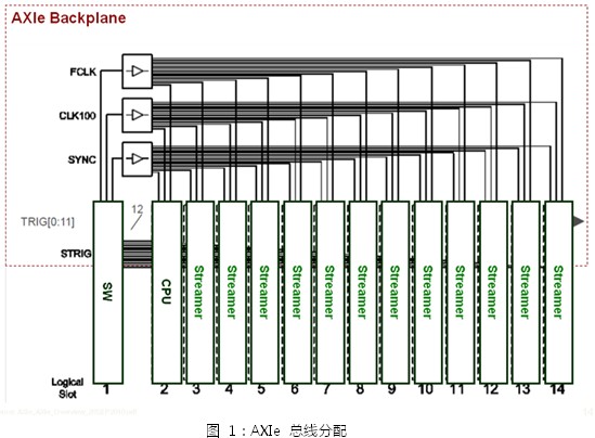
· Synchronization (synchronizaTIon) and local bus (local bus) function can provide the precise frequency required by each slot.

Graphics transmission architecture
The graphics transmission system includes a computer module, a PCIe converter module, multiple sets of data transmission modules, a 14-slot AXIe chassis, an external synchronization signal generator, and a disk array (RAID) system, as shown in Figure 2.
During e-beam printing, the computer module accesses the integrated circuit map file from the data center (that is, the disk array system) to the memory on the system in real time through the 6 Gbps SAS interface. The PCIe switch module is located in the hub slot and provides automatic PCIe channel switching. It is responsible for transferring the integrated circuit map files stored in memory to different data transmission modules through the PCIe high-speed data interface. Each transmission module can support 72 groups of fiber output channels. The external synchronization signal generator generates a set of common operating frequencies and trigger signals to allow multiple chassis to operate synchronously.
Most of AXIe's unique functions are adopted by the graphics transmission system, including: mechanism design and assembly, hardware platform management and monitoring mechanism, power distribution mechanism, active cooling system and data transmission interface.
In the E-Beam system chassis, for more complicated synchronization, it is necessary to use the AXIe STRIG and SYNC signals, which can ensure that the point trigger system achieves the extremely accurate and low jitter synchronization of each slot specified.
Easy Electronic Technology Co.,Ltd , https://www.nbpcelectronicgroup.com