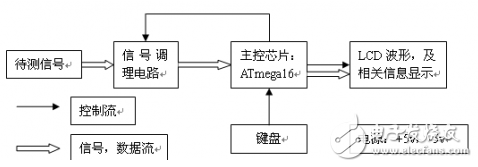
Figure 1 system structure
1.1, signal conditioning circuit
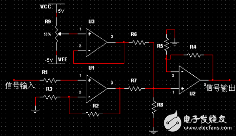
The function to be completed by the signal conditioning circuit is: program-controlled amplification, superimposing the DC component. The function of program-controlled amplification is to amplify the input signal when the amplitude of the input signal is small, so that the signal to be measured can be displayed as clearly as possible on the LCD. The effect of superimposing the DC component is: AT/16's own A/D is a single power supply, there is no way to input negative voltage and the signal to be tested often has negative pressure. At this time, a circuit is needed to raise the negative pressure above the 0 level.

Figure 2 signal conditioning circuit schematic
R1 and R2 are respectively connected to different resistors by an analog switch CD4051. Different R1 and R2 are passed the formula: thus the program-controlled amplification function can be realized. The adjustable resistor R9 is used to set the magnitude of the DC component added by the signal conditioning circuit. The amplified signal and DC component are finally superimposed by the U3 analog adder and output.
The relationship between the input signal and the output signal: As long as the resistance values ​​of R4, R6, and R7 are the same, the relationship between the input and output of the conditioning circuit is simplified to:
Ux is the output voltage of U3, and the voltage value of the output voltage is equal to the voltage of the tap of the intermediate resistor R9.
1.2, the main control chip software design
The main control chip of this system is selected, Atmel's AVR series microcontroller ATmega16, up to 16MPIS command speed. ATmega16 has 16K flash, 1K SRAM, 512 B EEPROM. The MCU has a 10-bit precision successive approximation analog-to-digital converter with built-in sample/hold circuit. The clock of the ADC is programmable. In this design, the clock of the 100KHz ADC is set to 2MHz for the highest sampling frequency. The trigger source for the ADC is selected as Timer/Counter 0 overflow, and the clock source for the ATmega16 timer is also programmable. This allows the ADC's sampling frequency to be controlled by controlling the Timer/Counter 0 overflow interrupt frequency.

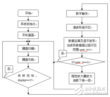
Figure 3 simple oscilloscope system program flow chart
1.2.1, keyboard function
In this system, seven buttons are set: run and stop, the magnification is increased, the magnification is decreased, the sampling frequency is increased, the sampling frequency is decreased, the trigger level is shifted up, and the trigger level is shifted down.
Run and Stop Keys: This is done by turning the ATmega16 ADC conversion interrupt on and off.
The increase and decrease of the magnification: the digital control of the magnification is realized by the ATmega16 control analog switch CD4051. The CD4051 is an 8-channel analog switch, so the programmable amplifier can have eight gears.
The increase and decrease of the sampling frequency: the sampling frequency required by the system is controlled by controlling the clock source of the Timer 0 of the ATmega16 and the initial value of the timer. The interrupt frequency of Timer 0 is equal to the sampling frequency of the ADC.
Up and down of the trigger level: When digitally triggering the sampled data, when the binary value of the data is increasing, the size of a certain data is just the same as the binary value of the digital trigger. Waveform data is stored in the display RAM.
When one of the 7 buttons is triggered, the corresponding flag bit is set to refresh the corresponding display information on the LCD screen.
1.2.3, digital trigger function
How to achieve triggering? The completion of the hardware will increase the complexity of the system hardware circuit, I thought of a way, there are software ways to achieve the trigger function. The process of implementation is as follows:
For (ik=0;ik<500;ik++){
If (k0_ram){
If (box_buff[ik] < trigger) {
Kk_ram = 1 ;
}
If (kk_ram){
If ((box_buff[ik] >= trigger) & (ik < 402)){
En_ram = 1 ;
K0_ram = 0 ;
Kk_ram = 0 ;
}}}
If (en_ram){
Boxing[adc_data]=box_buff[ik] ;
Adc_data++ ;
If (adc_data > 96){
Adc_data = 0x00 ;
En_ram = 0 ;
}}}
The size of the trigger can be set by the trigger level up and trigger level down buttons.
A TPU Screen Protector made of the super toughness of the honeycomb structure. Its unique ultra-soft properties allow it to cover the most complex curves and contours in a device.
The self-healing design of the Hydrogel Screen Protector can protect the display screen of the device from damage, leave no air bubbles, and maintain the sensitivity of the touch screen. Advanced anti-fingerprint and dust- and oleophobic overlays keep your screen smudge- and dirt-free. This overlay is also important in providing maximum touch sensitivity for improved high-speed glide and optimal touch response.
The optical transparency of the Hydrogel Film is more than 90%, showing you the most original screen color and bringing the most realistic visual experience.
If you want to know more about the product information of the Hydrogel Screen Protector for Huawei, please click the product details to view the parameters, model, picture, price and other information of the Huawei Screen Protector.
Whether you are a group or an individual, we will do our best to provide you with accurate and comprehensive information about Hydrogel Screen Protectors!
Screen Protector For Huawei,Hydrogel Film for Huawei,TPU Screen Protector for Huawei,Hydrogel Screen Protector for Huawei
Shenzhen Jianjiantong Technology Co., Ltd. , https://www.jjthydrogelprotector.com