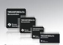
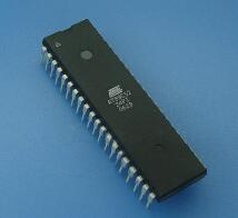
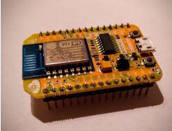
A Microcontroller Unit (MCU), also known as a Single Chip Microcomputer or a Single Chip Microcomputer, appropriately reduces the frequency and specification of a Central Processing Unit (CPU) and stores the memory (memory). , Counters (TImer), USB, A/D conversion, UART, PLC, DMA and other peripheral interfaces, and even LCD driver circuits are all integrated on a single chip to form a chip-level computer, and do different combination control for different applications. The MCU can be seen in mobile phones, PC peripherals, remote controls, automotive electronics, industrial stepper motors, and robot control.

To understand an MCU, the first thing to know is its ROM space, RAM space, the number of IO ports, the number of timers and timing modes, the provided Peripheral Circuits, interrupt sources, operating voltage, and power consumption.
After understanding these MCU Features, the next step is to compare the functions of the selected MCU with the requirements of the actual project development, clarifying what those resources are currently needed and those that are not used in this project. For the functions that are needed in the project and are not provided by the selected MCU, you need to carefully understand the MCU related data in order to achieve indirect methods. For example, the developed project needs to communicate with the PC COM port. If the selected MCU does not provide a UART port, it may consider using an external interrupt mode.
For the resources needed for project development, Manua* needs to be carefully understood and read, and unnecessary function modules can be ignored or browsed. For MCU learning, application is the key and the most important purpose.
Once you have clarified the related features of the MCU, you are ready to start programming. For beginners or designers who are using the MCU for the first time, there may be many places where the MCU's function description is not clear. For such problems, there are two ways to solve them. One is to write special verifications. Procedures to understand the functions described in the data; the other can be ignored temporarily, programming in accordance with their current understanding of the preparation, leaving to modify and improve when debugging. The former method is suitable for projects with less time and beginners, while the latter method is suitable for those who have certain MCU development experience or the project schedule is more pressing;
The instruction system must not take special time to understand. The instruction system is only a symbol of logic description. It is only necessary to view the relevant instructions according to their own logic and the logic requirements of the program during programming, and as the programming progresses, the instruction system will become more and more skilled, and even can Unconsciously memorize it.

For most MCUs, the following functions are the most common and basic. For different MCUs, the description may be different, but they are essentially the same:
â— TImer (timer): Although TImer is more types, it can be classified into two categories: one is a TImer with a fixed time interval, that is, its timing is set by the system, and the user program cannot be controlled. Provide several fixed time intervals for user program selection, such as 32Hz, 16Hz, 8Hz, etc. Such TImer is more common in 4-bit MCU, so it can be used to achieve clock, timing and other related functions; the other is Programmable Timer As the name implies, the timer's timing can be controlled by the user's program. The control methods include: clock source selection, Prescale selection, and prescale setting. And so on, some MCUs all have at the same time, while others may be one or two of them. Timer application of this kind is very flexible, and the actual use is also ever-changing. One of the most common applications is to use it to implement PWM output (specific applications, follow-up will have a special introduction). Since the clock source can be freely selected, such Timers are generally combined with the Event Counter.
â— IO port: Any MCU has a certain number of IO ports. Without an IO port, the MCU loses access to external communications. According to the configurable status of the IO port, it can be divided into the following types:
â— Pure input or pure output port: This IO port has the MCU hardware design decision, which can only be input or output. It cannot be set by software in real time.
â— Read and write IO port directly: For example, the IO port of MCS-51 belongs to this type of IO port. When the read IO port instruction is executed, it is the input port; when it executes the write IO port command, it is automatically the output port;
â— Program programming input and output direction: The input or output of this type of IO port is set by the program according to the actual needs, the application is more flexible, and it can realize some bus-level applications, such as I2C bus, various LCD, LED Driver control bus;
â— For the use of the IO port, it is important to keep in mind that: For the input port, there must be a clear level signal to ensure that it can not be floating (can be achieved by adding pull-up or pull-down resistors); and for the output port, its The output state level must take into account its external connection conditions. It should be ensured that there is no pull current or sink current in Standby or static state.
â— External interrupt: External interrupt is also the basic function of most MCUs. It is generally used for real-time signal triggering, data sampling and status detection. The interrupt mode is triggered by rising edge, falling edge trigger, and level trigger. The external interrupt is generally implemented through the input port. If it is an IO port, the interrupt function will only be enabled when it is set as an input; if it is an output port, the external interrupt function will be automatically shut down (the ATiny series of ATMEL has some exceptions, the output port Can also trigger the interrupt function). The application of external interrupts is as follows:
â— Detection of external trigger signals: One is based on real-time requirements, such as thyristor control, burst signal detection, and the other is the need for power saving;
Signal frequency measurement; In order to ensure that the signal is not missed, the external interrupt is the best choice;

â— Decoding of data: In the field of remote control applications, in order to reduce the cost of design, it is often necessary to use software to decode various encoded data, such as Manchester and PWM encoding;
â— Detection of keystrokes and system wake-up: For MCUs entering the Sleep state, they generally need to be woken up by an external interrupt. The most basic form is a keystroke, which generates a change in level by the action of a keystroke.
â— Communication Interface: The communication interfaces provided by the MCU generally include SPI interface, UART, I2C interface, etc., which are respectively described as follows:
â— SPI interface: This kind of interface is the most basic communication method that most MCUs provide. The data transmission is controlled by synchronous clock. The signals include: SDI (serial data input), SDO (serial data output), SCLK (serial clock) and Ready signal; In some cases there may be no Ready signal; this type of interface can work in Master mode or Slave mode. The popular saying is to see who provides the clock signal, and the party that provides the clock is Master, and vice versa. One is Slaver;
â— UART (Universal Asynchronous Receive Transmit): It is the most basic kind of asynchronous transmission interface. Its signal lines are only two Rx and Tx. The basic data format is: Start Bit + Data Bit (7-bits/8-bits) + Parity Bit (Even, Odd or None) + Stop Bit (1~2Bit). The time occupied by one bit of data is called Baud Rate. For most MCUs, the length of the data, the data check method (odd check, even check, or no check), the length of the stop bit (Stop Bit), and Baud Rate can be flexibly programmed. set. The most common way of such an interface is to communicate with the PC's serial port.
â— I2C interface: I2C is a data transmission protocol developed by Philips. It also uses two signals: SDAT (serial data input and output) and SCLK (serial clock). Its greatest advantage is that multiple devices can be connected to this bus, and the address is used for identification and access. One of the greatest benefits of the I2C bus is that it is very easy to use software to achieve through the IO port, and the data rate of its transmission is completely determined by the SCLK. To control, can be fast or slow, unlike UART interface, there are strict rate requirements.
â— Watchdog: The Watchdog is also a basic configuration of most MCUs (some 4-bit MCUs may not have this function). Most MCU watchdogs only allow the program to reset it and cannot Off (some are set when the program burns, such as the Microchip PIC series MCU), and some MCU is determined by a specific way to open it, such as Samsung's KS57 series, as long as the program access
The Watchdog register is automatically turned on and cannot be turned off. In general, the watchdog reset time can be set by the program. The most basic application of Watchdog is to provide a self-recovery capability for the MCU to crash due to an unexpected failure.
How to use MCU for simple function enhancementIf you have a 25-cent MCU, what can you do with 0.5KB of memory?
You may have used fixed-function integrated circuits (ICs) for a long time now, and in some cases, have adapted to their limited flexibility. A simple Universal Asynchronous Receiver Transmitter (UART)-to-Serial Peripheral Interface (SPI) bridge, a reset controller, or an external real-time controller (RTC) with backing memory performs well in its own function, but However, it is limited to the set function.
But if you can better meet your needs through intelligence or function customization? If you can use independent low-cost MCU to achieve these independent functions?
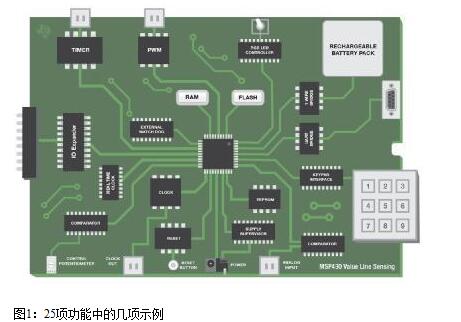
The new MSP430TM Value Sensing Series MCUs can help deploy simple sensing solutions with a variety of integrated mixed-signal capabilities. To expand the capabilities of these low-cost MCUs, TI created a library of code examples for 25 common system-level functions, including timers, input/output (I/O) expanders, system reset controllers, and electrically erasable programmable devices. Read memory (EEPROM) and so on.
The 25 functions are divided into four functional categories that are common in standard circuits: system management, pulse width modulation, timers, and communications. When using the MSP430FR2000 device, most of the code examples are suitable for memory below 0.5KB, the lowest cost MSP430 MCU is priced at as low as 1,000 units and 29 cents, and the number is as low as 25 cents. Figure 1 illustrates some of the discrete-function integrated circuits, such as external monitors or real-time clock ICs, that can be replaced with the corresponding ones of the 25 functions. If you use the multiple integrated circuits or functions shown (such as timers or PWMs), you can even combine multiple functions to meet your application needs, thereby reducing the workload and board space.

To help you understand and use these features, TI has produced an electronic version of the manual that contains 25 short application notes with a source code link. In a matter of minutes, the source code can be compiled, downloaded and run on the MSP430 Value Sensing Series MCUs. Functionality can be tailored to your application needs, dramatically reducing time to market.
As we begin to understand the programmable alternatives for many fixed-function ICs (we look forward to seeing what you can do with 25 functions), we will continue to build the application note series.
With the improvement of people's quality of life, people's lifestyles have also become varied. Different kinds of recreational products are starting to appear in people's lives, such as electronic cigarettes. The emergence of e-cigarettes represents a part of young people's thinking and means that electronic products are beginning to show a trend towards diversity.
simply replace the pods. The Pod system uses an integrated pod rather than a tank for higher nicotine strength and provides low power traction. the Pod system is rechargeable and has a longer life and higher battery capacity than disposable electronic cigarettes.
Our company Pod system has a built-in 380mAh battery and a USB charging port on the bottom. In comparison, the Pod system has a built-in battery of only 180mAh, but the Pod system charges much faster.
Our electronic cigarettes are of rechargeable construction. The first time you use the charger to charge, it is recommended to use up the remaining power before filling up, this is to ensure the performance of the battery.
Vape Pod System Oem,Vape Pod Oem,Close Pod Oem,Thc Pod Disposable
Shenzhen MASON VAP Technology Co., Ltd. , https://www.disposablevapepenfactory.com